21
Hardware Installation Guide for Cisco UCS E-Series Servers
OL-26447-03
Installing the E-Series Servers
Removing and Installing Blank Faceplates
Warning
Blank faceplates and cover panels serve three important functions: they prevent exposure to
hazardous voltages and currents inside the chassis; they contain electromagnetic interference (EMI)
that might disrupt other equipment; and they direct the flow of cooling air through the chassis. Do not
operate the system unless all cards, faceplates, front covers, and rear covers are in place.
Statement
1029
This section includes the following topics:
•
Removing the Blank Faceplates, page 21
•
Installing the Blank Faceplates, page 22
Removing the Blank Faceplates
Use this procedure to remove the blank faceplate from the router’s SM slot.
Procedure
Step 1
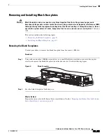
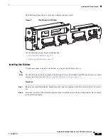
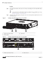
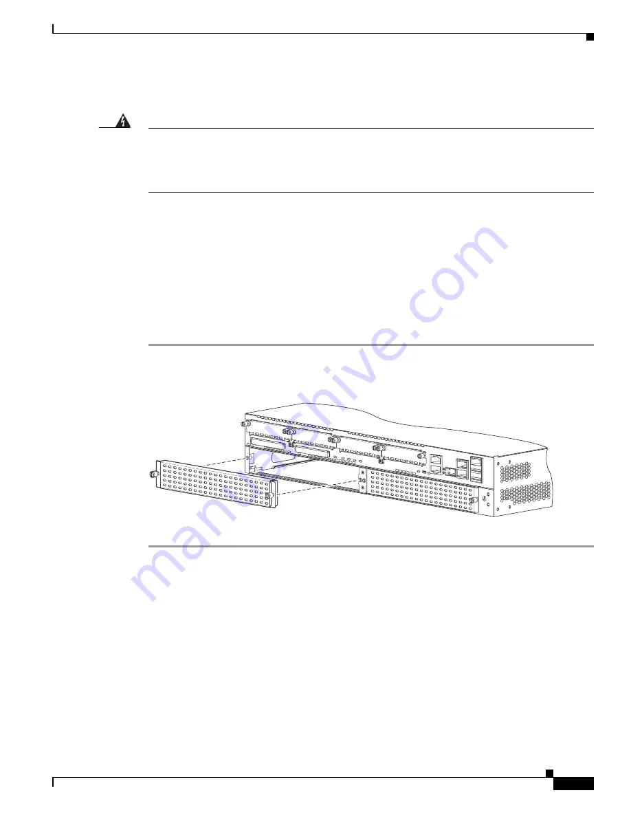
Using either a number 1 Phillips screwdriver or a small flat-blade screwdriver, unscrew the captive
screws and remove the blank faceplate from the chassis slot. See the following figure.
Figure 6
Blank Faceplate
Step 2
Save the blank faceplates for future use.
What to Do Next
Prepare the router slot for E-Series Server installation. See the
“Preparing the Router Slot for E-Series
Server Installation” section on page 22
.
DO NO
T REMO
VE DURING
NETWORK OPERA
TION
DO NO
T REMO
VE DURING
NETWORK OPERA
TION
2509
3
7


