3-23
Cisco UCS S3260 Storage Server Chassis Installation and Service Guide
Chapter 3 Maintaining the System
Installing or Replacing System Components
Replacing SAS/SATA Solid State Drives in the Rear Panel Bays
This section contains the following topics:
•
Rear-Panel SAS/SATA Solid State Drive Population Guidelines, page 3-23
•
Replacing Solid State Drives, page 3-23
Rear-Panel SAS/SATA Solid State Drive Population Guidelines
There are four bays for SAS/SATA SSDs in the rear panel. Drive numbering is shown in
populating these drives, follow these guidelines.
•
Server 1 SSD1 and SSD2 can be managed by server node 1. See also
Management Architecture, page 1-8
.
•
Server 2 SSD1 and SSD1 can be managed by server node 2.
•
Populate drives starting with the lowest-numbered bay to the highest within each server-controlled pair.
•
If a pair of SSDs is not present, keep the blanking panel in the empty two SSD bays to ensure proper air
flow (see
Identifying a Faulty Solid State Drive
Each solid state drive bay has a fault LED that lights solid amber to indicate a failing drive (see
).
Replacing Solid State Drives
Note
SAS/SATA solid state drives are hot-swappable and can be replaced without removing power from the system.
Step 1
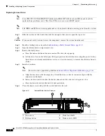
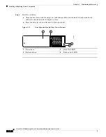
Remove a faulty solid state drive:
a.
Grasp and pinch the release latch toward the center.
b.
Pull the solid state drive straight out of the bay.
Step 2
Install a new solid state drive:
Note
Observe the drive population guidelines in
Rear-Panel SAS/SATA Solid State Drive Population
a.
Align the new drive with the empty bay (with the label facing up) and then push the drive in until it touches
the board connector.
b.
Grasp and pinch the release latch toward the center while you push the drive fully into the bay, and then
release the release latch.

