3-27
Cisco UCS S3260 Storage Server Chassis Installation and Service Guide
Chapter 3 Maintaining the System
Installing or Replacing System Components
Replacing a Disk Expansion Tray
The system can support one optional disk expansion tray, in server bay 2 only.
Tip
The tray contains one status LED (see
for the location and
definitions of the LED states).
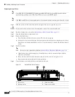
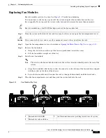
Figure 3-14
Disk Expansion Tray External Features (Four-Drive Version Shown)
Note
The disk expansion tray is hot-swappable, which means that you can remove it without shutting down
system power.
The disk expansion tray is accessed from the rear of the system, so you do not have to pull the system
out from the rack.
Step 1
Remove a disk expansion tray from the system:
a.
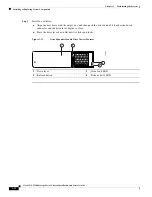
Grasp the two ejector levers and pinch their latches to release the levers (see
b.
Rotate both levers to the outside at the same time to evenly disengage the tray from the midplane
connectors.
c.
Pull the tray straight out from the system.
Step 2
Remove any drives from the old tray and move them to your new disk expansion tray. Install each drive
to the same position that it occupied in the old tray.
Step 3
Install a new disk expansion tray (server bay 2 only):
a.
With the two ejector levers open, align the new tray with the empty bay.
b.
Push the tray into the bay until it engages with the midplane connectors.
c.
Rotate both ejector levers toward the center until they lay flat and their latches lock into the rear of
the tray.
1
Disk expansion tray status LED
2
Disk expansion tray ejector levers (two)
353459
2
1


