9
VWIC-2MFT-T1-DIR, VWIC-2MFT-E1-DIR Installation Instructions
78-15842-01
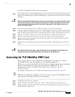
To install a T1/E1 Multiflex VWIC, follow this procedure:
Step 1
Power off the router by turning OFF the DC power source at the circuit breaker and taping the circuit
breaker into the OFF position. To channel ESD voltages to the ground, do not remove the wire from the
ground lug.
Warning
Before performing any of the following procedures, ensure that power is removed from the DC circuit.
To ensure that all power is OFF, locate the circuit breaker on the panel board that services the DC
circuit, switch the circuit breaker to the OFF position, and tape the switch handle of the circuit
breaker in the OFF position.
Step 2
Remove all network interface cables, including telephone cables, from the front panel.
Step 3
Use either a number 2 Phillips screwdriver or a small flat-blade screwdriver to remove the blank filler
panel from the network module slot where you plan to install the card. Save the filler panel for future use.
Step 4
Align the card with the guides in the two-slot network module and slide it gently into the slot.
Step 5
Push the card into place until you feel its edge connector mate securely with the connector.
Step 6
Fasten the card’s captive mounting screws into the holes in the network module faceplate using the
Phillips or flat-blade screwdriver.
Step 7
If the router was previously running, reinstall the network interface cables and turn on power to the
router.
Warning
After wiring the DC power supply, remove the tape from the circuit breaker switch handle and
reinstate power by moving the handle of the circuit breaker to the ON position.
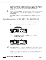
Connecting the T1/E1 Multiflex VWIC Card
How you connect the ports of the T1/E1 Multiflex VWIC depends on whether you are using the
Cisco MWR 1941-DC router in a redundant or a non-redundant configuration.
Whether you are using the Cisco MWR 1941-DC router in a redundant or non-redundant configuration
depends on the implementation of the router. For information on MWR 1941-DC router
implementations, see the
Cisco MWR 1941-DC Mobile Wireless Edge Router Software
Configuration Guide
.
For redundant configurations, use a Y-cable (as described in
Y-Cable Specifications, page 10
).
Note
HSRP must be configured for redundancy to allow one router to become active (CD LED on) and the
other to become the standby (AL LED on due to no framing).
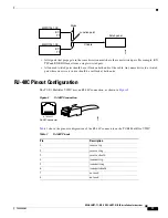
Step 1
Confirm that both routers are turned off.
Step 2
Connect the end of one of the Y-cable stubs to the T1 or E1 port on the card on the first router.
Step 3
Connect the end of the other Y-cable stub to the T1 or E1 port (using the same type of port as in
Step 2
)
on the card in the second router.

