background image

Page 13

CISSELL FORM FINISHER

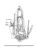
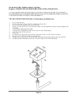
INSTRUCTIONS FOR ADJUSTING HEIGHT OF REVOLVING FORM

Should the revolving form “drag” on the Form Finisher base rather than turn freely, the form must be

raised.

Conversely, if the revolving form rides too high above the Form Finisher base, permitting steam to

escape from the space between the form and base, the form must be lowered.

WHEN AN ADJUSTMENT MUST BE MADE, REMOVE REVOLVING FORM BY SIMPLY LIFT-

ING IT STRAIGHT UP OFF THE FORM FINISHER BASE

PROBLEM:  Revolving Form “drags” on base of Form Finisher

TO CORRECT:  Loosen Bearing Lock Nut.

Turn Bearing Adjustment Screw COUNTER-CLOCKWISE.

CHECK ADJUSTMENT:  Replace revolving form on Form Finisher base.  Rotate form.  If perfectly

adjusted, form will rotate freely and snugly on felt seal around top of  base.  If form is still too low...or

too high...repeat adjustment until it is correct.

PROBLEM:  Revolving Form rides too high above Form Finisher base.

TO CORRECT:  Loosen Bearing Lock Nut.

Turn Bearing Adjustment Screw CLOCKWISE.

CHECK ADJUSTMENT:  Replacement revolving form on Form Finisher base.  Rotate

form.  If perfectly adjusted, form will rotate freely and snugly on felt seal around top of base.  If form

is still too high...or too low...repeat adjustment until it is correct.

Summary of Contents for FFCD

Page 1: ...Finisher Models FFCD FFCG THIS MANUAL MUST BE GIVEN TO THE EQUIPMENT OWNER CISSELLMANUFACTURINGCOMPANY HEADQUARTERS PHONE 502 587 1292 831SOUTHFIRSTST SALESFAX 502 585 3625 P O BOX32270 SERVICE PARTSF...

Page 2: ...r for any injury to persons or property or for any special or consequential damages The liability of Cissell does not include furnishing or paying for any labor such as that required to service remove...

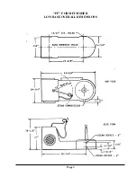
Page 3: ...Page 3 FF FORM FINISHER LOW BASE OVERALL DIMENSIONS...

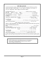
Page 4: ...6 6 1 32 m3 When ordering specify voltage desired CISSELL FORM FINISHER with Taller Revolving Assembly which differs from specifica tions for standard model given above Height 67 170 cm Net WeightAppr...

Page 5: ...a swing connection unions strainer trap check valve and 12 or more riser as illustrated on reverse side Inspect trap carefully for inlet and outlet markings and install swing connection trap and chec...

Page 6: ...Page 6...

Page 7: ...Finisher is now ready for operation REMOVE NYLON FORM from finisher at frequent intervals for cleaning as determined by its soiled condition WET clean only do NOT dryclean After wet cleaning the nylon...

Page 8: ...uired amount of steam and air within sleeves FRONT CLAMP For clamping front edges of sack coats jackets overcoats housecoats robes front buttoned dresses and blouses etc raises 5 for smallest child s...

Page 9: ...sted at front of machine from maximum to minimum or to any interme diate stage Markings 1 2 3 help operator to identify air pressure for repeat operations of similar garments FOR HEAVY GARMENTS keep a...

Page 10: ...m as steaming and drying is fully automatic 4 REMOVE COAT With AIR OFF withdraw sleevers relieving spring tension while withdrawing Release front and rear clamps Remove coat and place on hanger or pre...

Page 11: ...into the fabric while full air pressure holds the garment in expanded shape IMPORTANT WHEN EXTRA MOISTURE IS REQUIRED USE A WATER SPRAY GUN during the steam cycle holding the spray gun about 15 from...

Page 12: ...shoulder to its smallest width Do not open dress zippers or buttons with AIR ON as this may change the shape and natural drape of the dress Grasp shoulders of dress lift upward and slide dress from f...

Page 13: ...rm Finisher TO CORRECT Loosen Bearing Lock Nut Turn BearingAdjustment Screw COUNTER CLOCKWISE CHECK ADJUSTMENT Replace revolving form on Form Finisher base Rotate form If perfectly adjusted form will...

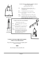
Page 14: ...th Finger pack inside of dome above ball bearing B1 with Valve SealA TO REPLACE METALLIC STEAM SPREADER Form Finisher Serial No 100 To FIRST Remove old metallic spreader if it fails to diffuse steam p...

Page 15: ...solenoid energized or manually held closed so that solenoid armature gap 0 set the push rod gap at 1 16 Tighten the lock nut against the push rod end PRESSURE CONTROL ADJUSTMENT With damper closed bl...

Page 16: ...Page 16...

Page 17: ...Page 17...

Page 18: ...d frame N and P the lower draw cable will not operate properly TO INSTALLNYLON BAG FIRST Slip bag over form with Cissell label at front Be certain that right draw cables within bag hand at right side...

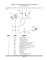
Page 19: ...PU8 1 4 Compression Bead 7 F636 Adapter Fitting w Lock Nut Hose Adapter 8 SG114 4 4 Water Hose Ass y w rubber bumper 9 SGO43 Water Spray Gun Only overhead 10 F590 Water Spray Gun Holder for Overhead S...

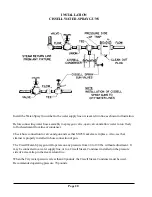
Page 20: ...tion to valve and gun and see that SG25 Gaskets are in place Also see that strainer is properly installed in hose connection of gun The Cissell Water Spray gun will operate on any pressure from 40 to...

Page 21: ...ea Water HoseAssembly Includes fittings gaskets and ferrules at each end of hose Part No Description SG114 4 4 Long SG37 5 Long SG68 7 Long SG115 9 9 Long SG87 11 Long SG155 20 Long WATER SPRAYGUN PI...

Page 22: ...f 6 12 V 36 RenewableValve Seat 13 V 15 Small Lock Nut Pkg 0f 6 14 V 16 Teflon Disc 15 FV 104 Valve Disc Holder 16 V 330 Spring Pkg 0f 6 17 FV 105 Valve Spring Retainer K451 Repair Kit for FV111 Valve...

Page 23: ...No No Description 25 F303 Hip Lower Index Plate 26 F302 Control Slides 27 F332 Front Plate 28 F333 Front Latch 29 F104 Trigger Release 30 F335 Clamp Latch Rod 31 F151 Compression Latch Spring 32 F137...

Page 24: ...in 14 F429 Tension Spring 15 F439 D Lever Rod Hip F1056 G Lever Rod Hip WAIST HIP AND LOWER CONTROLS FOR MODELS D G Ref Part No No Description 16 F440 Lever Rod Waist 17 040113282 Bead Chain 18 F442 N...

Page 25: ...Nut 4 A ground wire is not required If one exists on the Form Finisher cut off the terminal and prepare end of wire by wrapping it with electrical tape 5 Cover end of pipe with threaded plastic bushi...

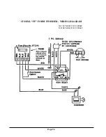
Page 26: ...Page 26 CISSELL FF FORM FINISHER WIRING DIAGRAM 110 VOLT 60 50 CYCLE 1 PHASE 220 VOLT 60 50 CYCLE 1 PHASE...

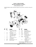
Page 27: ...ff with speed nuts and stove bolts 1 5 F 368 Blower Wheel 1 6 F 369 Blower Housing with cut off 7 F 371 Bearing Assembly Ref Part No No Description 8 F 372 Thrust Collar 1 9 F 373 Bearing Insulator Cu...

Page 28: ...OTE IF INSTALLATION HAS BEEN MADE ACCORDINGTO INSTRUCTIONSTHE BELTALIGN MENT SHOULD BE CORRECT IF THERE SHOULD BEANY DOUBT CHECK THE FOLLOWING IN STRUCTIONS A Place a straight edge against face of Lar...

Page 29: ...W A Ref Part No No Description 10 F 186 Solenoid Extension Arm 11 F 732 Steam Control Lever 12 F 739H Solenoid 115V Only F 738H Solenoid 230V Only 13 F 682 Throwout Cam Plate 14 F 1175 Damper Push Rod...

Page 30: ...trical parts espe cially the solenoid Replace if necessary Check power source and be sure it matches voltage phase and fre quency specified on machine nameplate Inspect solenoid Replace if it is burne...

Page 31: ...achine and repair or replace any leaking parts See leaking steam valve above Inspect timer and be sure the motor will run and the switches operate properly If not repair or replace timer Inspect timer...

Page 32: ...tions and check to see that bag strings are untangled and properly connected Increase pressure in the bag with the pressure control lever Check to see that belt is properly aligned and tight accordin...

Page 33: ...ower shaft is straight if not replace it Check to see that shaft is tight but free to turn in brgs If brgs have very loose fit on shaft replace bearings Run motor with V belt removed and check by feel...

Reviews: