
Page 27
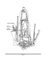
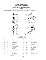
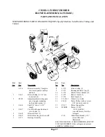
CISSELL FORM FINISHER
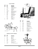
BLOWER ASSEMBLY(LOW BASE)
PARTS AND INSTALLATION
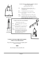
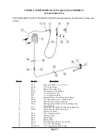
WHEN ORDERING PARTS OR MAKING INQUIRY, Specify Machine, Serial Number, Voltage and
Current.
Ref.
Part
No.
No.
Description
F-734
Blower Assembly Complete
less motor, guards, pulleys
and belt
1
F-363
Blower Pulley (1) 3/4 dia.
hole (AK-61)
2
PT332
Adjustment Bolt with square
nut, strap pad, mounting
bolt, nut and washer (1)
3
F-366
Shaft 3/4 dia. x 16 1/2
length
4
F-367
Cut-off (with speed nuts and
stove bolts) (1)
5
F-368
Blower Wheel (1)
6
F-369
Blower Housing (with cut-off)
7
F-371
Bearing Assembly
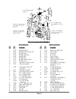
Ref.
Part
No.
No.
Description
8
F-372
Thrust Collar (1)
9
F-373
Bearing Insulator Cup (2)
10
F-374
Plastic Thrust Washer (2)
11
F-375
Blower Guard (1)
12
F-376
Belt Guard (1)
13
TU-2317
V-Belt (1) 4L-380
14
F1034
Motor Pulley with set screw
5/8 dia. hole (AK-34)
15
PT-47
Motor Support Bar
16
MTR88
Motor 1/2 HP
115/230/60/50/1
(consult factory for other
voltages)
P-36
Allen Head Wrench, 5/32
across flats (not
illustrated)
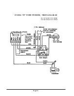
ELECTRIC MOTOR -- WHEN ORDERING, SPECIFY
VOLTAGE DESIRED. Other voltages and currents
available at additional cost.
Summary of Contents for FFCD
Page 3: ...Page 3 FF FORM FINISHER LOW BASE OVERALL DIMENSIONS...
Page 6: ...Page 6...
Page 16: ...Page 16...
Page 17: ...Page 17...


