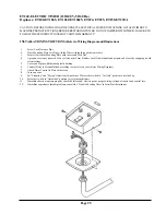
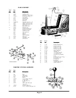

Page 29
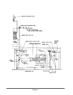
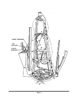
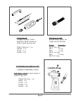
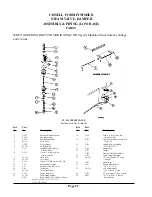
BASE ASSEMBLY
Ref.
Part
No.
No.
Description
1
SG043
Water Spray Gun
2
F565
Housing W/A (specify color)
3
TU3549
Rubber Bumper (Pkg. of 3)
4
F149
Valve Pull Rod
5
F539
Steam Chamber
6
F357
Felt Air Seal
7
F1187
Steam Coil
8
5046000249
Greenfield Cable - 3/8 x 18
9
F678
Damper Control Wire Tube
F679
Damper Control Wire Only
10
FG235
Motor Relay (115 V.)
FG234
Motor Relay (230 V.)
11
ET240
Electronic Timer
ET234
Timer Replacement Fuse
12
F686
Support Pipe Assembly
F999
Support Pipe Only
F995
Timer Case Only
F94
Lock Nut
F717
Bushing
F590
Spray Gun Holder
13
F1000
Front Cover
14
F720
Solenoid Box Cover
15
F719
Low Base W/A
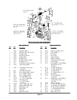
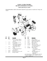
Ref.
Part
No.
No.
Description
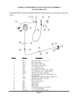
10
F-186
Solenoid Extension Arm
11
F-732
Steam Control Lever
12
F-739H
Solenoid 115V. Only
F-738H
Solenoid 230V. Only
13
F-682
Throwout Cam Plate
14
F-1175
Damper Push Rod
F-388
Hardened Tip
15
F-362
X Washers (Pkg. of 6)
16
F-489
E Rings (Pkg. of 6)
17
F-724
Throwout Lever Assembly
18
F-692
Spring
19
F-664
Swivel w/Screw and E Ring
20
F-990
Roll Pin (Pkg. of 6)
21
F-185
Extension Bar
22
F-254
Bearing Plate
23
TU-49
Delrin Bearing (Pkg. of 2)
24
F-215
Collar w/Set Screw
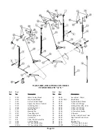
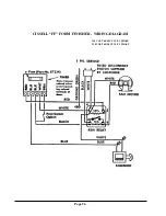
DAMPER CONTROL ASSEMBLY
Ref.
Part
No.
No.
Description
1
D16
Knob
2
F750
Shaft w/Nuts
3
F660
Rubber Washer
4
F663
Bracket
5
TU4934
1/4 - 20 Hex Nut (Pkg. of 6)
6
F639
Friction Washer
7
F358
E Ring (Pkg. of 6)
8
F664
Swivel
9
SV332
#8-32 x 3/8 Rd. Hd. Screw
(Pkg. of 6)
10
TU2847
Flat Washer (Pkg. of 6)
11
RC344
1/4 - 20 x 3/4 Hex Screw (Pkg. of 6)
Summary of Contents for FFCD
Page 3: ...Page 3 FF FORM FINISHER LOW BASE OVERALL DIMENSIONS...
Page 6: ...Page 6...
Page 16: ...Page 16...
Page 17: ...Page 17...