Power-Up
Once the VT-100 program is set up, plug the unit into an AC outlet. The device begins a series of self-
diagnostic tests, which are displayed as a series of LED flashes.
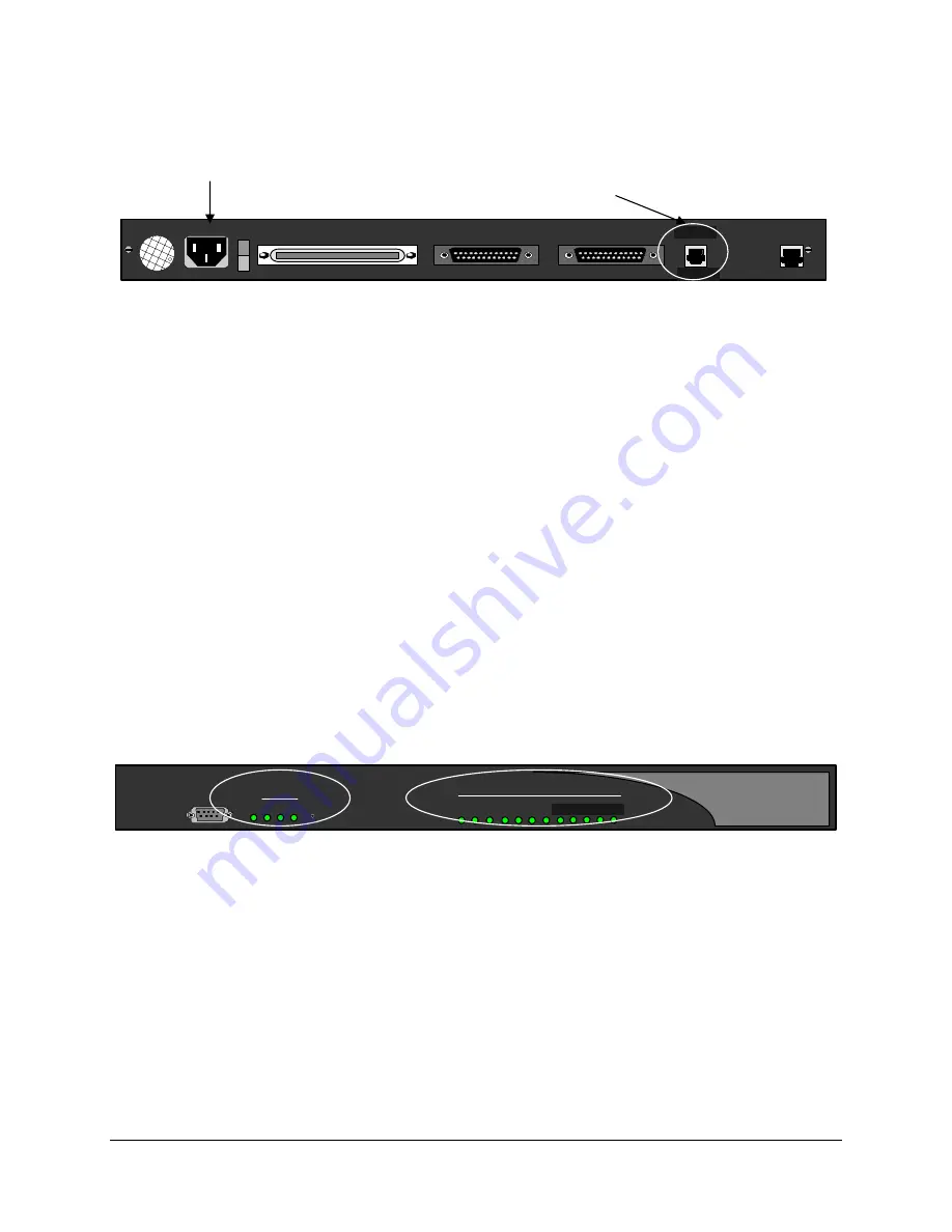
AC Power
LAN
Connection
LNK
CLN
ANALOG LAN
0
TELEPHONY INTERFACE
WAN 1
WAN 2
100-240 V ~ 0.8A 50-60 HZ
LNK ACT
LAN
Figure 5:
Back of Unit (LAN Connections)
LAN Notes:
If you are connecting an Extender to an IP network, the unit requires an IP address. The Ethernet port on
the Remote Unit operates on 10 and 100 megabit Ethernet networks. On power-up, if the Ethernet cable
is connected to a network device the Remote Unit will auto-detect whether the network is using 10 or 100
megabit Ethernet. If the network cable is not connected the Remote Unit will default to using 10 megabit
Ethernet. In this case you will need to either manually configure the Ethernet mode to force 10 or 100
megabit Ethernet or power-cycle the Remote Unit with the network cable connected in order to auto-
detect the 100 megabit Ethernet connection.
Once the power-up sequence is finished, the state of the following LEDs should be Green.
LED States:
Solid Green.
PWR
WAN1
Solid Green (Ready) if a synchronous device is connected to WAN 1.
Solid Orange (Ready) if an asynchronous ISDN TA is connected and accepting
commands (but there is no link up- in Call Suspend mode or has not dialed it yet).
Solid Green if connected properly to the PBX.
Port LEDs
IMPORTANT:
If any of the LEDs DO NOT power as explained, refer to the System Administrator’s
Guide for troubleshooting information.
PWR and WAN 1
Connected Ports
LNK
CLN
3
1 2
7
6
5
4
Port Status
PWR 1
3
2
Console
WAN
Reset
8 9 10 11 12
Figure 6:
Front of Unit
On initial power-up (or before the config file is changed) the Management Interface (MI) asks you to run
the “Setup Wizard”.
EXTender™ IP6000 Quick Installation Guide
21


