BD2-2880/2890 User’s Manual
5
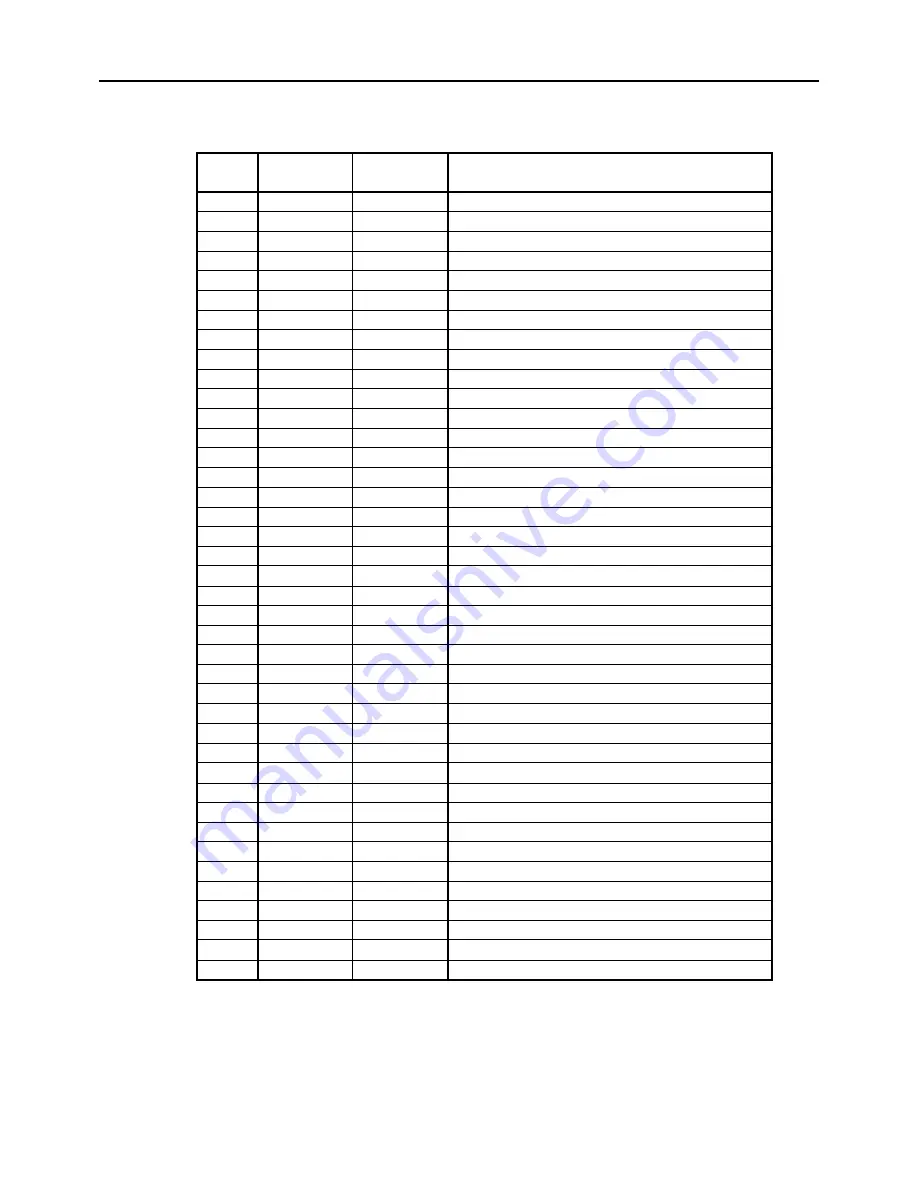
3.3 CN3 Connector for Interface
1
2
3
4
5
6
7
8
9
10
11
12
13
14
15
16
17
18
19
20
21
22
23
24
25
26
27
28
29
30
31
32
33
34
35
36
37
38
39
40
Vcc
Vcc
GND
GND
Vp
Vp
Vp
Vp
Vp
Vp
P-GND
P-GND
P-GND
P-GND
P-GND
P-GND
LF-SW
ERROR
PEout
DTR
TXD
RXD
DSR
DATA0
DATA1
DATA2
DATA3
DATA4
DATA5
DATA6
DATA7
STB
BUSY
FAULT
SELECT
PE
NC
NC
SELECTIN
RESET
––
––
––
––
––
––
––
––
––
––
––
––
––
––
––
––
Input
Output
Output
Output
Output
Input
Input
Output
Output
Output
Output
Output
Output
Output
Output
Output
Output
Output
Output
Output
Output
––
––
Input
Function
Power supply for circuit (5V)
Power supply for circuit (5V)
GND
GND
Power supply for operation
Power supply for operation
Power supply for operation
Power supply for operation
Power supply for operation
Power supply for operation
GND for operation
GND for operation
GND for operation
GND for operation
GND for operation
GND for operation
LF Switch input
ERROR LED output (Can be connected directly)
PE LED output (Can be connected directly)
Serial Interface DTR
Serial Interface TXD
Serial Interface RXD
Serial Interface DSR
Parallel Interface DATA0
Parallel Interface DATA1
Parallel Interface DATA2
Parallel Interface DATA3
Parallel Interface DATA4
Parallel Interface DATA5
Parallel Interface DATA6
Parallel Interface DATA7
Parallel Interface STB
Parallel Interface BUSY
Parallel Interface FAULT
Parallel Interface SELECT
Parallel Interface PE
Parallel Interface ACK
No Connection
No Connection
Parallel Interface RESET
Pin No.
Signal Name
I/O
Applicable Connector : 53313 - 4015 (Molex)


