background image

CBM-202PC User’s Manual 


31           

CITIZEN 


Summary of Contents for CBM-202PC Series

Page 1: ...USER S MANUAL Model CBM 202PC Series Control LSI for Citizen Thermal Printer Mechanism Rev 1 0 November 1st 1996 Rev 1 1 February 2nd 1997 Japan CBM Corporation Information Systems Div...

Page 2: ...bject to changes without prior notification 2 Upon finding of any inappropriateness error or omission concerning contents of this manual please contact us at any time 3 Notwithstanding the above Item...

Page 3: ...4 3 6 HEAD UP DETECTION CIRCUIT 15 3 7 HEAD DETECTION CIRCUIT 16 3 8 PAPER END DETECTION CIRCUIT 17 3 9 MOTOR CONTROL CIRCUIT 18 3 10 AUTO CUTTER CONTROL CIRCUIT 19 3 11 PARALLEL INTERFACE CIRCUIT 20...

Page 4: ...CBM 202PC User s Manual 4 CITIZEN 8 2 INTERNATIONAL CHARACTER CODE TABLE 40...

Page 5: ...4 Bar code printing is available 5 Prints such as double width double high and bit image printing are available by various commands 1 1 MODEL CLASSIFICATIONS LSI Chip Model name Applied Printer Mechan...

Page 6: ...ine Type No of Digits Total No of Dots Character Size mm Print Speed m s LT 282 37 448 50 LT 283 34 416 50 LT 380 48 576 50 LT 381 48 576 1 25 3 00 Font A 0 88 2 13 Font B 50 2 5 OPERATING VOLTAGE AND...

Page 7: ...to AVcc 0 3V Operating temperature Topr 20 to 75 Storage temperature Tstg 55 to 125 3 2 ELECTRICAL CHARACTERISTICS ITEM SYMBOL MIN MAX UNIT CONDITION RES STBY NMI MDO MD1 MD2 Vcc 0 7 Vcc 0 3 V EXTAL V...

Page 8: ...NC NC 8 DRQ I DMA request LOW 9 NC NC 10 RESO O Watchdog output LOW 11 VSS GND 12 DTR O Serial DTR RS 232C HIGH 13 TXD O Serial TXD RS 232C HIGH 14 DI I Print head output data HIGH 15 RXD I Serial RX...

Page 9: ...H 30 D3 I O D3 HIGH 31 D4 I O D4 HIGH 32 D5 I O D5 HIGH 33 D6 I O D6 HIGH 34 D7 I O D7 HIGH 35 VCC VCC 36 A0 O A0 HIGH 37 A1 O A1 HIGH 38 A2 O A2 HIGH 39 A3 O A3 HIGH 40 A4 O A4 HIGH 41 A5 O A5 HIGH 4...

Page 10: ...61 O NC 60 P62 O NC 61 O Clock output HIGH 62 STBY I Pull up in VCC with 10K LOW 63 RES I Reset input LOW 64 NMI I Pull up in VCC with 10K LOW 65 VSS GND 66 EXTAL EXTAL 16 MHz 67 XTAL XTAL 16 MHz 68 V...

Page 11: ...I Pull down in GND with 10K 85 NC I Pull down in GND with 10K 86 AVSS GND 87 STB I Parallel data interrupt LOW 88 HEADUP I Headup detection terminal LOW 89 CS2 O Gate array chip selection LOW 90 CS1...

Page 12: ...data D5 HIGH 47 D4 I Parallel input data D4 HIGH 48 D3 I Parallel input data D3 HIGH 49 D2 I Parallel input data D2 HIGH 50 D1 I Parallel input data D1 HIGH 51 D0 I Parallel input data D0 HIGH 52 STR...

Page 13: ...RES terminal set to Low reset state is created In order to assure resetting it is necessary to hold Low for min 20ms on supply of power and for min 625ns while in operation When external reset is not...

Page 14: ...ble including one to connect a ceramic oscillator and the other to input an external clock When using a ceramic oscillator you are recommended to use CSTCS16 00MX0C3 with a condenser manufactured by M...

Page 15: ...s supplied in head up state with the head up sensor installed in the printer With head UP it becomes OPEN With head DOWN it becomes CLOSE In head UP state CPU s HEADUP Pin 88 gets HIGH where printing...

Page 16: ...ed by temperature This function through use of a thermistor installed in the printer detects temperature based on which energy applied to the head is determined Further when head temperature has excee...

Page 17: ...he paper sensor which is installed in the paper not to supply power when paper runs our Without printing paper CPU PAPER Pin 99 gets HIGH When this takes place while in printing operation the operatio...

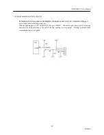
Page 18: ...paper feed the motor is held unexcited by CPU INH Pin 97 so that heating of the motor is prevented While INH is held in HIGH the motor is maintained unexcited On supply of power 4 dot lines of line fe...

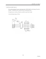
Page 19: ...3 10 AUTO CUTTER CONTROL CIRCUIT This CPU by using the gate array CBM 202LA has auto cutter control function When an auto cutter is not used set DS1 1 to OFF When DS1 1 is ON alarm state is created wh...

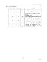
Page 20: ...ms 8 bit parallel interface by mainly using the gate array ports When the parallel interface is not used pull up STB Pin 52 of the gate array CBM 202LA through use of 10K resistance Also either connec...

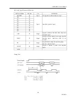
Page 21: ...46 D6 45 D7 44 Input Input data positive logic ACK 59 Output Signal to indicate that data have been read negative logic BUSY 55 Output Signal to indicate that data receiving is possible positive logic...

Page 22: ...02PC User s Manual 22 CITIZEN 3 12 SERIAL INTERFACE CIRCUIT Serial interface applies asynchronous serial system When not using serial interface pull up CPU s RXD Pin 15 and DSR Pin 100 with 10K resist...

Page 23: ...Input Receiving data signal On occurrence of a framing error or parity error the data are printed in DSR 100 Input With this signal held in LOW when data are transmitted from CPU while DTR DSR has bee...

Page 24: ...for printer paper feeding Also a function for self printing is equipped through use of this switch Either supply power as pushing this switch or apply resetting in power supplied state as pushing this...

Page 25: ...t an appropriate current control resistance LED etc CPU s LEDPE Pin 4 is exclusively for output of paper error When printing paper has got scarce LOW is output automatically When paper is supplied it...

Page 26: ...election LF Ignored 31 PAI2 Print density See Table 30 PAI3 DTR XON XOFF XON XOFF DTR DSR 29 PAI4 28 PAI5 27 PAI6 26 PAI7 Interface See Table PAI 3 is valid only when serial interface is used GATE ARR...

Page 27: ...OW 2400 HIGH HIGH LOW HIGH 4800 HIGH HIGH LOW LOW 9600 HIGH LOW HIGH HIGH None 19200 HIGH LOW HIGH LOW 1200 HIGH LOW LOW HIGH 2400 HIGH LOW LOW LOW 4800 LOW HIGH HIGH HIGH 9600 LOW HIGH HIGH LOW Odd 1...

Page 28: ...PBI1 PBI0 Japan JIS HIGH HIGH HIGH Japan Shift JIS HIGH HIGH LOW Sweden HIGH LOW HIGH Denmark I HIGH LOW LOW U K LOW HIGH HIGH Germany LOW HIGH LOW France LOW LOW HIGH U S A LOW LOW LOW Print Density...

Page 29: ...CBM 202PC User s Manual 29 CITIZEN 3 16 EXTERNAL RAM INTERFACE An external SRAM of 32 K bytes is always necessary for printing When no external RAM is connected normal operation cannot be obtained...

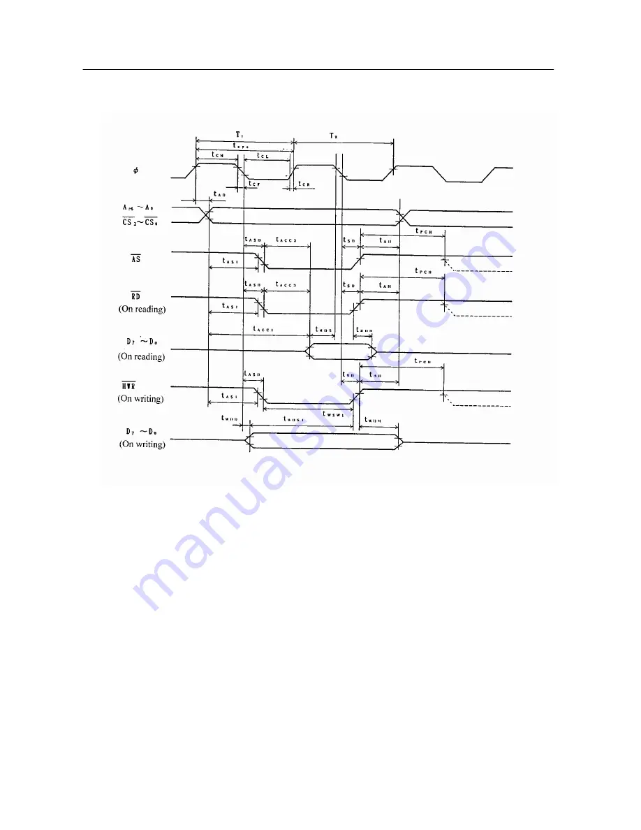
Page 30: ...D 30 Address hold time tAH 10 Address strobe delay time tASD 30 Write strobe delay time tWSD 30 Strobe delay time tSD 30 Write data strobe pulse width 1 tWSW1 35 Write data strobe pulse width 2 tWSW2...

Page 31: ...CBM 202PC User s Manual 31 CITIZEN...

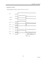
Page 32: ...CBM 202PC User s Manual 32 CITIZEN 4 OPERATING TIMING Operating timing after resetting is canceled for this CPU is shown below...

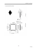
Page 33: ...CBM 202PC User s Manual 33 CITIZEN 5 PACKAGE SPECIFICATIONS...

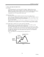
Page 34: ...y surface tension of the reflowed solder Although the design value of the lead joint part pattern on a PCB board varies by soldering paste material reflow conditions etc the standard level is 1 1 to 1...

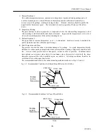
Page 35: ...sity to maintain the peak temperature and time within the specific range 4 Peak Temperature and Time The greatest care must be taken to minimize damage of a package As a peak temperature directly infl...

Page 36: ...oisture absorption Absorbed moisture content as it gets high can suddenly vaporize on soldering implementation causing peeling of resin lead frame joint or even causing a crack on a package It is ther...

Page 37: ...ter 1BH40H 13 D Setting horizontal tab position 1BH44H n k00H 14 E Specifying canceling highlighting 1BH45Hn 15 G Specifying canceling double printing 1BH47Hn 16 J Printing and feeding paper n 203 inc...

Page 38: ...ode 1DH48Hn 34 f Selecting the font of HRI code 1DH66Hn 35 Defining the download bit image 1DH2An1n2 d n1xn2x 36 Printing the download bit image 1DH2FHm 37 Starting ending macro definition 1DH3AH 38 E...

Page 39: ...CBM 202PC User s Manual 39 CITIZEN 8 CHARACTER CODE TABLE 8 1 INTERNATIONAL...

Page 40: ...CBM 202PC User s Manual 40 CITIZEN 8 2 INTERNATIONAL CHARACTER CODE TABLE...

Reviews: