Chapter 3 Disassembly and Maintenance
3-6. Disassembly, Reassembly and Lubrication
CL-E700 series
3-22
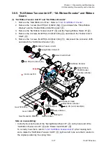
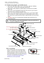
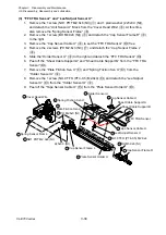
(2) “SA Ribbon Tension Shaft F” and “SA Ribbon Sensor”
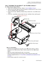
1. Remove the “Bush Ribbon Roller” (2 pcs.) on both sides, detach the “SA Ribbon
Tension Shaft F”, and peel off the “Sheet Static Eliminator 621”.
2. Remove the 2 screws (No0 PH(4-0.3) M2x3 (NI)) (
) and detach the “SA Ribbon
Sensor” (
).
3. Remove the 1 screw (PH(PW) M2.0x8 (NI)) (
) and remove the “Lever F Tension
Adjust” Block (
) and “Shaft Tension Adjust” (
).
4. Remove the 2 screws (No0 (BT4x0.5)M1.7x4 (NI)) from the “Lever F Tension Adjust”
Block and detach the “Holder2 Tension Spring” and “Spring Ribbon Tension” (2 pcs.).
Also, remove the 2 screws (No0 (BT4x0.5)M1.7x4 (NI)) and detach the “Knob Tension
Adjust”.
5.
If required,
remove the 1 screw (No0 PH(4-0.3) M2x3 (NI)) and detach the “Cam
Tension Base Adjust”.
Do not remove the “Cam Tension Base Adjust” unless you need to. Once it
is removed, readjustment is required.
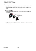
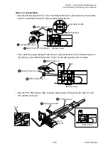
Note on reassembling:
• When remounting the “Cam Tension Base Adjust”,
align the + mark of the “Cam Tension Base Adjust”
with the scribe line as shown on the right (The “Cam
Tension Base Adjust” is set to the mechanical center.)
Next, perform the adjustment according to “
Front side “Cam Tension Base Adjust” position
adjustment (For service personnel)
”.
Lever F Tension Adjust
PH(PW) M2.0x8 (NI)
No0 PH(4-0.3) M2x3 (NI)
Cam Tension Base Adjust
No0 PH(4-0.3) M2x3 (NI)
Bush Ribbon Roller
Bush Ribbon Roller
Sheet Static Eliminator 621
SA Ribbon Tension Shaft F
No0 (BT4x0.5)M1.7x4 (NI)
Knob Tension Adjust
Spring Ribbon Tension
Holder2 Tension Spring
Shaft Tension Adjust
J606
SA Ribbon Sensor Frame F
SA Ribbon Sensor
[Do not remove unless you need to.]
[Do not remove unless you need to.]
1
2
3
4
5
Cam Tension Base Adjust
Scribe line
Summary of Contents for CL-E700 Series
Page 1: ...Technical Manual CL E700 series Thermal Transfer Printer...
Page 5: ...Chapter 1 Specifications 1 1 CL E700 series CHAPTER 1 SPECIFICATIONS...
Page 15: ...Chapter 2 Operating Principles 2 1 CL E700 series CHAPTER 2 OPERATING PRINCIPLES...
Page 87: ...Chapter 3 Disassembly and Maintenance 3 1 CL E700 series CHAPTER 3 DISASSEMBLY AND MAINTENANCE...
Page 151: ...Chapter 4 Troubleshooting 4 1 CL E700 series CHAPTER 4 TROUBLESHOOTING...
Page 167: ...Chapter 5 Parts Lists CL E700 series CHAPTER 5 PARTS LISTS...
Page 172: ...Chapter 5 Parts Lists CL E700 series 5 6 DRAWING NO 1 General Assembly Rev 0...
Page 195: ...Chapter 5 Parts Lists 5 29 CL E700 series DRAWING NO 7 Unit Opepane Rev 0...
Page 203: ...Chapter 5 Parts Lists 5 37 CL E700 series DRAWING NO 9 SA2 Ribbon Unit Fan Rev 0...
Page 206: ...Chapter 5 Parts Lists CL E700 series 5 40 DRAWING NO 10 Accessories Rev 0 3 2 4 1 1 1 2 1 3...
Page 208: ...Chapter 6 Circuit Diagrams 6 1 CL E700 series CHAPTER 6 CIRCUIT DIAGRAMS...
Page 230: ...Appendices AP 1 CL E700 series APPENDICES...
Page 233: ...Appendices A Mounting Diagrams CL E700 series AP 4 2 Solder side...

