Chapter 3 Disassembly and Maintenance
3-6. Disassembly, Reassembly and Lubrication
3-
39
CL-E700
series
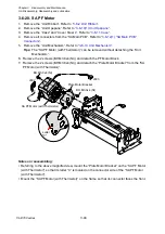
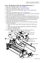
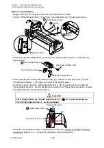
3-6-19. “SA Head”, “Cam Head Adjust” and “Cam Head Balance”
When detaching or reinstalling the “SA Head”, be careful not to damage the thermal
elements. Especially, avoid contacting the thermal elements with a metal part, etc.
Do not touch the thermal elements of the “SA Head” with your bare hand.
(1) “SA Head” Block
1. Remove the “Unit Ribbon”. Refer to “
”.
2. Remove the “Unit Opepane”. Refer to
”.
3. Remove the “Case” and “Cover Steel L”. Refer to “
4. Remove all connectors from the “SA Main PCB”. Refer to “
5. Remove the “Unit Mechanism”. Refer to “
6. Remove the “Unit Head”. Refer to “
3-6-18 “Unit Head” and “Unit PF”
”.
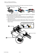
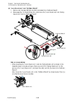
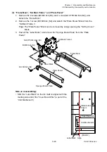
7. Place the “Unit Head” upside down as shown below.
8. Remove the 2 screws (BH M3.0x6 (NI)) and detach the “Guide Head Cable”.
9. To make removal easy, set both dials (Media width adjustment dial and Media
thickness adjustment dial) to “5”.
10. While pressing down the “SA Head” Block, first move it forward and then to the left to
remove it. Refer to the arrows in the figure.
11. Disconnect the connector from the “SA Head” Block, remove the 2 screws (BH M3.0x3
(NI) and BH M3.0x6 (NI)), and remove the “SA Head Cable”.
Caution
BH M3.0x6 (NI)
Guide Head Cable
Unit Head
SA Head Cable
BH M3.0x6 (NI)
BH M3.0x3 (NI)
(Media Width Adjustment Dial)
(Media Thickness Adjusment Dial)
"5"
"5"
"SA Head" Block
Summary of Contents for CL-E700 Series
Page 1: ...Technical Manual CL E700 series Thermal Transfer Printer...
Page 5: ...Chapter 1 Specifications 1 1 CL E700 series CHAPTER 1 SPECIFICATIONS...
Page 15: ...Chapter 2 Operating Principles 2 1 CL E700 series CHAPTER 2 OPERATING PRINCIPLES...
Page 87: ...Chapter 3 Disassembly and Maintenance 3 1 CL E700 series CHAPTER 3 DISASSEMBLY AND MAINTENANCE...
Page 151: ...Chapter 4 Troubleshooting 4 1 CL E700 series CHAPTER 4 TROUBLESHOOTING...
Page 167: ...Chapter 5 Parts Lists CL E700 series CHAPTER 5 PARTS LISTS...
Page 172: ...Chapter 5 Parts Lists CL E700 series 5 6 DRAWING NO 1 General Assembly Rev 0...
Page 195: ...Chapter 5 Parts Lists 5 29 CL E700 series DRAWING NO 7 Unit Opepane Rev 0...
Page 203: ...Chapter 5 Parts Lists 5 37 CL E700 series DRAWING NO 9 SA2 Ribbon Unit Fan Rev 0...
Page 206: ...Chapter 5 Parts Lists CL E700 series 5 40 DRAWING NO 10 Accessories Rev 0 3 2 4 1 1 1 2 1 3...
Page 208: ...Chapter 6 Circuit Diagrams 6 1 CL E700 series CHAPTER 6 CIRCUIT DIAGRAMS...
Page 230: ...Appendices AP 1 CL E700 series APPENDICES...
Page 233: ...Appendices A Mounting Diagrams CL E700 series AP 4 2 Solder side...

