Chapter 3 Disassembly and Maintenance
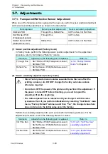
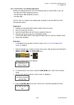
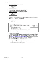
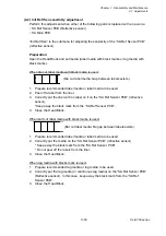
3-6. Disassembly, Reassembly and Lubrication
CL-E700 series
3-40
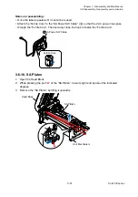
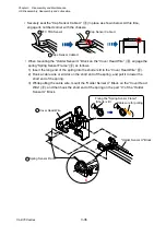
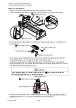
Note on reassembling:
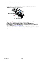
When mounting the “SA Head”, follow the next procedure.
1. Set the dials as follows.
Media width adjustment dial:
“0” (for easier mounting)
Media thickness adjustment dial: “9”
2. Put the entire “SA Head” Block in the frame and move it to the direction “
”.
At this time, be sure that the screw “
A
” is inserted into the slit “
B
”. (If it is not correctly
inserted, the “SA Head” Block cannot be assembled on the frame.)
3. While lightly pressing down the “SA Head” Block (
), move it toward the rear (
) and
hook its rear ends on the 2 claws “
C
” of the frame.
4. After mounting the “SA Head” Block, set the Media width adjustment dial to “5” to give
tension to the “SA Head” Block.
Claw
C
Screw
A
Slit
B
1
2
2
3
3
"SA Head" Block
(Media Width Adjustment Dial)
(Media Thickness Adjusment Dial)
"0"
"9" to "5"
Summary of Contents for CL-E700 Series
Page 1: ...Technical Manual CL E700 series Thermal Transfer Printer...
Page 5: ...Chapter 1 Specifications 1 1 CL E700 series CHAPTER 1 SPECIFICATIONS...
Page 15: ...Chapter 2 Operating Principles 2 1 CL E700 series CHAPTER 2 OPERATING PRINCIPLES...
Page 87: ...Chapter 3 Disassembly and Maintenance 3 1 CL E700 series CHAPTER 3 DISASSEMBLY AND MAINTENANCE...
Page 151: ...Chapter 4 Troubleshooting 4 1 CL E700 series CHAPTER 4 TROUBLESHOOTING...
Page 167: ...Chapter 5 Parts Lists CL E700 series CHAPTER 5 PARTS LISTS...
Page 172: ...Chapter 5 Parts Lists CL E700 series 5 6 DRAWING NO 1 General Assembly Rev 0...
Page 195: ...Chapter 5 Parts Lists 5 29 CL E700 series DRAWING NO 7 Unit Opepane Rev 0...
Page 203: ...Chapter 5 Parts Lists 5 37 CL E700 series DRAWING NO 9 SA2 Ribbon Unit Fan Rev 0...
Page 206: ...Chapter 5 Parts Lists CL E700 series 5 40 DRAWING NO 10 Accessories Rev 0 3 2 4 1 1 1 2 1 3...
Page 208: ...Chapter 6 Circuit Diagrams 6 1 CL E700 series CHAPTER 6 CIRCUIT DIAGRAMS...
Page 230: ...Appendices AP 1 CL E700 series APPENDICES...
Page 233: ...Appendices A Mounting Diagrams CL E700 series AP 4 2 Solder side...

