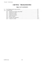
Chapter 4 Troubleshooting
4-2. Troubleshooting
4-7
CL-E700 series
4-2-3. Problems in Printing
Symptoms
Checks
Remedies
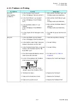
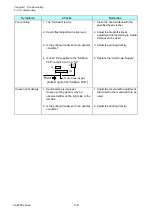
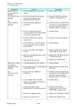
No print
(Overheating
problems)
1. Is the “SA Head” over heated?
(The LCD displays “Alarm Head Hot”.)
2. Is the “SA PF Motor” over heated?
(The LCD displays “Error PFMotor
Hot”.)
3. Is the “SA Ribbon Motor F” over
heated?
(The LCD displays “Error RBMotor
Hot”.)
4. Is “Error System Fail” displayed on the
LCD?
1. Wait until the “SA Head” gets cool.
Printing resumes automatically.
2. Wait until the “SA PF Motor” gets
cool.
Printing resumes automatically.
3. Wait until the “SA Ribbon Motor F”
gets cool.
Printing resumes automatically.
4. Turn OFF the power and then turn
it ON.
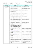
No print
1. Is the head block securely closed?
(The LCD displays “Error Head Open”.)
2. Is the interface cable firmly connected
between the printer and the host?
3. Is the “SA Head Cable” firmly connected
between the “SA Head” and the “SA
Main PCB” (J2)?
4. Does the transparent/reflective sensor
detect presence of media?
5. Is +24V DC supplied to the “SA Main
PCB” (at pins 6 to 9 of J13)?
J5
To Unit Power Supply
Front
J13
J2
1
9
[Bottom right of the “SA Main PCB”]
6. “SA Head” is broken.
7. Failure in the head driver circuit.
8. Failure in the control circuit.
1. Close the head block correctly.
2. Connect it firmly.
3. Connect it firmly.
4. To check, see “
5. Replace the “Unit Power Supply”.
6. Replace the “SA Head”.
7. Replace the “SA Head”.
8. Replace the “SA Main PCB”.
Summary of Contents for CL-E700 Series
Page 1: ...Technical Manual CL E700 series Thermal Transfer Printer...
Page 5: ...Chapter 1 Specifications 1 1 CL E700 series CHAPTER 1 SPECIFICATIONS...
Page 15: ...Chapter 2 Operating Principles 2 1 CL E700 series CHAPTER 2 OPERATING PRINCIPLES...
Page 87: ...Chapter 3 Disassembly and Maintenance 3 1 CL E700 series CHAPTER 3 DISASSEMBLY AND MAINTENANCE...
Page 151: ...Chapter 4 Troubleshooting 4 1 CL E700 series CHAPTER 4 TROUBLESHOOTING...
Page 167: ...Chapter 5 Parts Lists CL E700 series CHAPTER 5 PARTS LISTS...
Page 172: ...Chapter 5 Parts Lists CL E700 series 5 6 DRAWING NO 1 General Assembly Rev 0...
Page 195: ...Chapter 5 Parts Lists 5 29 CL E700 series DRAWING NO 7 Unit Opepane Rev 0...
Page 203: ...Chapter 5 Parts Lists 5 37 CL E700 series DRAWING NO 9 SA2 Ribbon Unit Fan Rev 0...
Page 206: ...Chapter 5 Parts Lists CL E700 series 5 40 DRAWING NO 10 Accessories Rev 0 3 2 4 1 1 1 2 1 3...
Page 208: ...Chapter 6 Circuit Diagrams 6 1 CL E700 series CHAPTER 6 CIRCUIT DIAGRAMS...
Page 230: ...Appendices AP 1 CL E700 series APPENDICES...
Page 233: ...Appendices A Mounting Diagrams CL E700 series AP 4 2 Solder side...


