Chapter 2 Operating Principles
2-1.
Operation of Each Mechanism
2-13
CL-E700 series
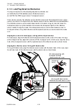
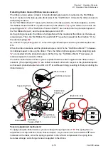
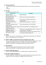
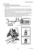
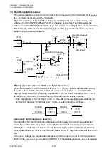
Detecting ribbon tension (Ribbon tension sensor):
The ribbon tension sensor consists of two photointerrupters and is mounted on the “SA Ribbon
Sensor” located on the take-up side (front side) of the “Unit Ribbon”. It detects the ribbon tension to
adequately control it.
As the “SA Ribbon Motor F” takes up the ribbon on the take-up side, the ribbon tightens, and the
“SA Ribbon Tension Shaft F” is pushed inward (in the direction “
a
”) by the ribbon. As a result, the
projecting parts “
A
” of the “SA Ribbon Tension Shaft F” are inserted into the photointerrupters of
the “SA Ribbon Sensor”, and the photointerrupters turn OFF.
As the printing proceeds, the ribbon is fed together with the media and the ribbon on the take-up
side slackens. Then, the “SA Ribbon Tension Shaft F” is pushed outward (in the direction “
b
”) by
the internal springs “
B
”.
As a result, the projecting parts “
A
” come off the photointerrupters and the photointerrupters turn
ON.
When the ribbon slackens and the photointerrupters turn ON, the “SA Ribbon Motor F” increases
its rotational speed to take up the ribbon. Then, the ribbon tightens again and the projecting parts
“
A
” are inserted into the photointerrupters. At this time, the “SA Ribbon Motor F” decreases its
rotational speed to loosen the ribbon.
The above ribbon tension control cycle is repeated and the tension applied to the ribbon is kept
constant. (The projecting parts “
A
” are shifted a bit each other with respect to the photointerrupters
so that each photointerrupter turns ON or OFF at a different timing, resulting in finely controlling the
ribbon tension.)
Tension adjustment mechanism:
To apply adequate ribbon tension, you can change the spring force of “
B
”. The spring force is
adjustable in 3 steps with the “Knob Tension Adjust”. As you move the knob toward the
mark
indicated on the label, since the spring is pushed to the left and compressed, the spring force
becomes stronger and stronger tension is applied to the ribbon.
KnobTension
Adjustment
SA Ribbon Sensor
Supporting Point
SA Ribbon
Tension Shaft F
Spring Ribbon
Tension (2 pcs.)
Ribbon
A
[Right side view]
a
b
B
Ribbon Sensor
A
Ribbon
Summary of Contents for CL-E700 Series
Page 1: ...Technical Manual CL E700 series Thermal Transfer Printer...
Page 5: ...Chapter 1 Specifications 1 1 CL E700 series CHAPTER 1 SPECIFICATIONS...
Page 15: ...Chapter 2 Operating Principles 2 1 CL E700 series CHAPTER 2 OPERATING PRINCIPLES...
Page 87: ...Chapter 3 Disassembly and Maintenance 3 1 CL E700 series CHAPTER 3 DISASSEMBLY AND MAINTENANCE...
Page 151: ...Chapter 4 Troubleshooting 4 1 CL E700 series CHAPTER 4 TROUBLESHOOTING...
Page 167: ...Chapter 5 Parts Lists CL E700 series CHAPTER 5 PARTS LISTS...
Page 172: ...Chapter 5 Parts Lists CL E700 series 5 6 DRAWING NO 1 General Assembly Rev 0...
Page 195: ...Chapter 5 Parts Lists 5 29 CL E700 series DRAWING NO 7 Unit Opepane Rev 0...
Page 203: ...Chapter 5 Parts Lists 5 37 CL E700 series DRAWING NO 9 SA2 Ribbon Unit Fan Rev 0...
Page 206: ...Chapter 5 Parts Lists CL E700 series 5 40 DRAWING NO 10 Accessories Rev 0 3 2 4 1 1 1 2 1 3...
Page 208: ...Chapter 6 Circuit Diagrams 6 1 CL E700 series CHAPTER 6 CIRCUIT DIAGRAMS...
Page 230: ...Appendices AP 1 CL E700 series APPENDICES...
Page 233: ...Appendices A Mounting Diagrams CL E700 series AP 4 2 Solder side...

