Chapter 2 Operating Principles
2-1.
Operation of Each Mechanism
2-17
CL-E700 series
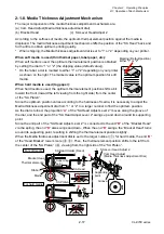
2-1-8. Media Thickness Adjustment Mechanism
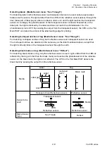
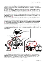
The major components of the media thickness adjustment mechanism are:
(a) Cam Head Adjust (Media thickness adjustment dial)
(b) Bracket Head
(c) SA Lever Head Adjust 2
According to the softness of media, the optimum thermal element position against the media is
displaced. The media thickness adjustment mechanism shifts the position of the “SA Head” back and
forth a little to obtain optimum printing quality.
* When shipping, the Media thickness adjustment dial is set to “1” or “2” depending on your printer.
When soft media is used (thin thermal paper, label paper, etc.):
When soft media is used, the optimum thermal element position is obtained
by setting the dial to “1” or “2” (the shipping value (default value)).
* On the label, a dot is marked to either “1” or “2” depending on your printer
as shown on the right. The marked value is the optimum position for soft
media.
When hard media is used (tag paper):
When hard media is used, the optimum thermal element position shifts a bit
toward the front (toward the left viewing from the right side) from the center
of the “SA Platen”.
Since the optimum position varies according to the hardness of media, it is necessary to adjust the
Media thickness adjustment dial from “1” or “2” to a larger number to find the optimum position.
As the dial is turned, the projection “
A
” of the “SA Head Adjust Lever 2” moves along the groove of
the dial, and the end part of the “SA Head Adjust Lever 2” swings up and down around its supporting
point.
Since the end part of the “SA Head Adjust Lever 2” is connected to the end “
B
” of the “Bracket Head”
via the spring, the end “
B
” also swings and down. When the end “
B
” swings, the “Bracket Head” turns
around its supporting point, resulting in shifting the thermal element position slightly.
When the Media thickness adjustment dial is set to the larger number (
) for hard media, the end “
B
”
of the “Head Bracket” lowers more (
,
). Then, the thermal element position shifts to the left from
the center of the “SA Platen” (
), viewing from the right side of the “SA Platen”.
Marking (Default position)
Either "1" or "2"
Ribbon
Supporting
point
For soft media
For hard media
SA Platen
Media
SA Head
Thermal elements
SA Lever Head Adjust 2
SA Head Holder (Fixed)
Bracket Head
Supporting
point
Groove
B
B
0
9
1
2
3
0
9
4
9
0
Cam Head Adjust
(Media Thickness Adjustment Dial)
A
Summary of Contents for CL-E700 Series
Page 1: ...Technical Manual CL E700 series Thermal Transfer Printer...
Page 5: ...Chapter 1 Specifications 1 1 CL E700 series CHAPTER 1 SPECIFICATIONS...
Page 15: ...Chapter 2 Operating Principles 2 1 CL E700 series CHAPTER 2 OPERATING PRINCIPLES...
Page 87: ...Chapter 3 Disassembly and Maintenance 3 1 CL E700 series CHAPTER 3 DISASSEMBLY AND MAINTENANCE...
Page 151: ...Chapter 4 Troubleshooting 4 1 CL E700 series CHAPTER 4 TROUBLESHOOTING...
Page 167: ...Chapter 5 Parts Lists CL E700 series CHAPTER 5 PARTS LISTS...
Page 172: ...Chapter 5 Parts Lists CL E700 series 5 6 DRAWING NO 1 General Assembly Rev 0...
Page 195: ...Chapter 5 Parts Lists 5 29 CL E700 series DRAWING NO 7 Unit Opepane Rev 0...
Page 203: ...Chapter 5 Parts Lists 5 37 CL E700 series DRAWING NO 9 SA2 Ribbon Unit Fan Rev 0...
Page 206: ...Chapter 5 Parts Lists CL E700 series 5 40 DRAWING NO 10 Accessories Rev 0 3 2 4 1 1 1 2 1 3...
Page 208: ...Chapter 6 Circuit Diagrams 6 1 CL E700 series CHAPTER 6 CIRCUIT DIAGRAMS...
Page 230: ...Appendices AP 1 CL E700 series APPENDICES...
Page 233: ...Appendices A Mounting Diagrams CL E700 series AP 4 2 Solder side...

