Chapter 2 Operating Principles
2-2.
Operation of Control Parts
CL-E700 series
2-34
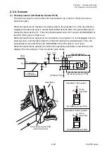
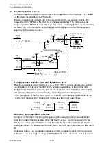
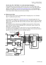
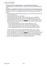
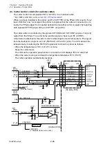
Forcible stop of the “SA Ribbon Motor F” at an abnormally high temperature:
If the temperature of the “SA Ribbon Motor F” reaches 85
C (185
F), the “SA Ribbon Motor F”
stops.
In addition, an abnormally high temperature is monitored by the abnormally high temperature
detection circuit. (Refer to “
2-2-4(5) Ribbon motor temperature sensor
”.) If the abnormally high
temperature (100
C (212
F)) is detected with this circuit, the FPGA controls the circuits as
follows.
• Changes the level at pin N3 (VMT ON) from “High” to “Low” so that +24V DC (VMT) to the
motor driver (U601) stops.
• Stops the output from the motor driver (U601).
From the temperature error detection circuits, the following error signals nTMPERR
(abnormally high temperature errors) are output to the NAND gate (U11). If any of the
following abnormally high temperature errors occurs, the error signal nTMPERR changes
from “High” level to “Low” level. Thus, pin 2 (ENABLE) of the motor driver (U601) goes to
“High” level to stop its outputs.
• An abnormally high temperature error from the head temperature sensor
• An abnormally high temperature error from the PF motor temperature sensor
• An abnormally high temperature error from the ribbon motor temperature sensor
• An abnormally high temperature error from the cutter temperature sensor (option)
Further, the output from pin 5 of monostable multivibrator (U6B) is used as another
condition to forcibly stop the “SA Ribbon Motor F”. If an edge input sent from the CPU
(U1A) to the U6B stops for some reason, pin 5 of U6B goes to “Low” level and the output of
U11 goes to “High” level. As a result, pin 2 (ENABLE) of the motor driver (U601) goes to
“High” level to stop its outputs for safety. This forcible function prevents the “SA Ribbon
Motor F” from being damaged even if an abnormal condition happens.
Summary of Contents for CL-E700 Series
Page 1: ...Technical Manual CL E700 series Thermal Transfer Printer...
Page 5: ...Chapter 1 Specifications 1 1 CL E700 series CHAPTER 1 SPECIFICATIONS...
Page 15: ...Chapter 2 Operating Principles 2 1 CL E700 series CHAPTER 2 OPERATING PRINCIPLES...
Page 87: ...Chapter 3 Disassembly and Maintenance 3 1 CL E700 series CHAPTER 3 DISASSEMBLY AND MAINTENANCE...
Page 151: ...Chapter 4 Troubleshooting 4 1 CL E700 series CHAPTER 4 TROUBLESHOOTING...
Page 167: ...Chapter 5 Parts Lists CL E700 series CHAPTER 5 PARTS LISTS...
Page 172: ...Chapter 5 Parts Lists CL E700 series 5 6 DRAWING NO 1 General Assembly Rev 0...
Page 195: ...Chapter 5 Parts Lists 5 29 CL E700 series DRAWING NO 7 Unit Opepane Rev 0...
Page 203: ...Chapter 5 Parts Lists 5 37 CL E700 series DRAWING NO 9 SA2 Ribbon Unit Fan Rev 0...
Page 206: ...Chapter 5 Parts Lists CL E700 series 5 40 DRAWING NO 10 Accessories Rev 0 3 2 4 1 1 1 2 1 3...
Page 208: ...Chapter 6 Circuit Diagrams 6 1 CL E700 series CHAPTER 6 CIRCUIT DIAGRAMS...
Page 230: ...Appendices AP 1 CL E700 series APPENDICES...
Page 233: ...Appendices A Mounting Diagrams CL E700 series AP 4 2 Solder side...

