Chapter 2 Operating Principles
2-2.
Operation of Control Parts
2-37
CL-E700 series
(5)
Fan driver
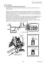
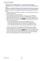
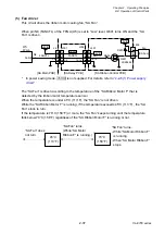
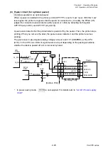
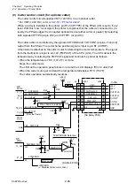
This circuit drives the ribbon motor cooling fan, “SA Fan”.
When pin N8 (FANCTL) of the FPGA (U5) is set to “Low” level, Q601 turns ON and the “SA
Fan” is driven.
* In power saving mode, +5VIO is not supplied. For details, refer to “
”.
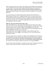
The “SA Fan” is driven according to the temperature of the “SA Ribbon Motor F” that is
detected by the ribbon motor temperature sensor.
When the temperature is under 45
C (113
F), the “SA Fan” is not driven.
While the “SA Ribbon Motor F” is running, if the temperature exceeds 45
C (113
F) , the “SA
Fan” starts to turn.
If the temperature is 70
C (158
F) or more, the “SA Fan” keeps turning until the temperature
falls below 70
C (158
F) regardless of the “SA Ribbon Motor F” is running or not.
D601
Q601
R604
2SK3664
+5VIO
+5VIO
1
2
J604
[SA Main PCB]
34-N8
N8
9
2
J601
[SA Ribbon Control PCB]
FANCTL
9
2
14-16
[SA Fan]
14-16
J304
J301
3-6
3-6
J4
[SA Relay PCB]
20
7
20
7
FANCTL
FANCTL
FPGA
U5
+5VIO
Fan
+5VIO
“SA Fan” turns.
- While “SA Motor Ribbon F”
is running.
- When “SA Motor Ribbon F”
stops.
“SA Fan” turns.
(While “SA Motor
Ribbon F” is running.)
“SA Fan” does
not turn.
70
C
(158
F)
45
C
(113
F)
Summary of Contents for CL-E700 Series
Page 1: ...Technical Manual CL E700 series Thermal Transfer Printer...
Page 5: ...Chapter 1 Specifications 1 1 CL E700 series CHAPTER 1 SPECIFICATIONS...
Page 15: ...Chapter 2 Operating Principles 2 1 CL E700 series CHAPTER 2 OPERATING PRINCIPLES...
Page 87: ...Chapter 3 Disassembly and Maintenance 3 1 CL E700 series CHAPTER 3 DISASSEMBLY AND MAINTENANCE...
Page 151: ...Chapter 4 Troubleshooting 4 1 CL E700 series CHAPTER 4 TROUBLESHOOTING...
Page 167: ...Chapter 5 Parts Lists CL E700 series CHAPTER 5 PARTS LISTS...
Page 172: ...Chapter 5 Parts Lists CL E700 series 5 6 DRAWING NO 1 General Assembly Rev 0...
Page 195: ...Chapter 5 Parts Lists 5 29 CL E700 series DRAWING NO 7 Unit Opepane Rev 0...
Page 203: ...Chapter 5 Parts Lists 5 37 CL E700 series DRAWING NO 9 SA2 Ribbon Unit Fan Rev 0...
Page 206: ...Chapter 5 Parts Lists CL E700 series 5 40 DRAWING NO 10 Accessories Rev 0 3 2 4 1 1 1 2 1 3...
Page 208: ...Chapter 6 Circuit Diagrams 6 1 CL E700 series CHAPTER 6 CIRCUIT DIAGRAMS...
Page 230: ...Appendices AP 1 CL E700 series APPENDICES...
Page 233: ...Appendices A Mounting Diagrams CL E700 series AP 4 2 Solder side...

