Chapter 2 Operating Principles
2-2.
Operation of Control Parts
CL-E700 series
2-46
(9)
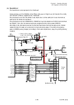
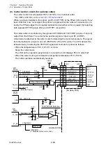
Cutter control circuit (for optional cutter)
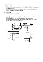
The cutter control circuit supplies VMT (+24V DC) to an optional cutter.
* For VMT (+24V DC), refer to “
When a cutter is installed in the printer, pin D12 (CPTYP0) of the FPGA (U5) is set to “Low”
level. With this “Low” level signal, the printer recognizes that the cutter is connected to. (In
reality, the FPGA judges the connected optional device (either cutter or peeler) by detecting
both signals CPTYP0 (at pin D12) and CPTYP1 (at pin D9)).
The cutter action is controlled by the signals CUTCON0 and CUTCON1 (at pins J1 and J2)
output from the FPGA. The cutter home position signal is input to pin B1 (CUTHP).
A thermistor is attached to the cutter motor for detecting the motor temperature. The signal
from the thermistor is input to pin 100 (TMPCUT) of the CPU (U1A). The CPU detects the
temperature by monitoring the TMPCUT signal and controls the printer as follows.
• When the temperature is 78
C (172.4
F) or more:
Stops the cutter motor.
The LED on the operation panel blinks in red and the LCD displays “Error Cutter Fail”.
• When the cutter motor get cold and the temperature falls below 70°C (158°F):
The cutter operation automatically resumes.
J302
Cutter
3
2
1
5
4
7
6
8,9,10
VMT
AN6
CPTYP0
74_D12
D12
R59
C98
R65
+3.3V
L: When Cutter is installed.
R60
+3.3V
C97
R66
R64
R61
J2
CUTCON0
J1
21_J1
22_J2
CUTCON1
+24V
+24V
CUTCTL0
CUTCTL1
CUTHP
CUTTH
GND
CPRTYP0
CUTHP
100
TMPCUT
(+24V)
9
2
1
11
10
13
12
9
2
1
11
10
13
12
J4
J301
3-6
3-6
VMT
VMT
CUTCON_0
CUTCON_1
CUT_HP
TMP_CUT
OPTION TYPE_0
[SA Relay PCB]
R62
R63
F1
B1
11_B1
CPU
FPGA
U5
U1A
U8B
-
+
5
6
7
+3.3V
[SA Main PCB]
TEMP ERROR Detection
BA2903SFVM
R34
+3.3V
R38
C60
R40
A15
K1
71_A15
21_K1
FPGA
nTMPERR
TMPENB_CUT
Error: Low
U5
nTMPERR
C96
TMPCUT
(L: Disables ribbon motor drive.)
CPTYP1
74_D9
D9
(from the Peeler)
Summary of Contents for CL-E700 Series
Page 1: ...Technical Manual CL E700 series Thermal Transfer Printer...
Page 5: ...Chapter 1 Specifications 1 1 CL E700 series CHAPTER 1 SPECIFICATIONS...
Page 15: ...Chapter 2 Operating Principles 2 1 CL E700 series CHAPTER 2 OPERATING PRINCIPLES...
Page 87: ...Chapter 3 Disassembly and Maintenance 3 1 CL E700 series CHAPTER 3 DISASSEMBLY AND MAINTENANCE...
Page 151: ...Chapter 4 Troubleshooting 4 1 CL E700 series CHAPTER 4 TROUBLESHOOTING...
Page 167: ...Chapter 5 Parts Lists CL E700 series CHAPTER 5 PARTS LISTS...
Page 172: ...Chapter 5 Parts Lists CL E700 series 5 6 DRAWING NO 1 General Assembly Rev 0...
Page 195: ...Chapter 5 Parts Lists 5 29 CL E700 series DRAWING NO 7 Unit Opepane Rev 0...
Page 203: ...Chapter 5 Parts Lists 5 37 CL E700 series DRAWING NO 9 SA2 Ribbon Unit Fan Rev 0...
Page 206: ...Chapter 5 Parts Lists CL E700 series 5 40 DRAWING NO 10 Accessories Rev 0 3 2 4 1 1 1 2 1 3...
Page 208: ...Chapter 6 Circuit Diagrams 6 1 CL E700 series CHAPTER 6 CIRCUIT DIAGRAMS...
Page 230: ...Appendices AP 1 CL E700 series APPENDICES...
Page 233: ...Appendices A Mounting Diagrams CL E700 series AP 4 2 Solder side...

