Chapter 2 Operating Principles
2-3.
Operation Panel
CL-E700 series
2-52
(3)
Menu list print mode
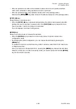
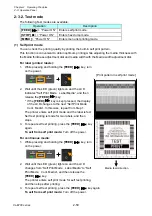
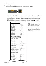
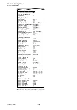
You can print the list of machine information and current menu settings.
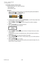
1. While pressing and holding the
[MENU]
key, turn on the power.
2. When the LED (green) lights on and the LCD indicates “Print Settings”, release the
[MENU]
key.
The printer prints the menu list in continuous mode and the list of machine information and
current menu settings are printed. Then the printer enters menu setup mode for further
menu operation.
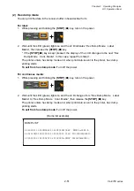
To exit from menu list print mode:
In Main menu, press the
[PAUSE]
( ) key twice.
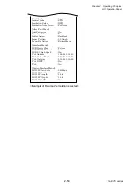
Machine Information
Model Number
: CL-E720
Serial Number
: **-*******
Boot Version
: *.*
ROM Version
: ********
ROM Date(DD/MM/YY)
: **/**/**
ROMCheck Sum
: ****
FPGA Version
: ***.***
Head Check
: OK
Print Counter
: 0002.2km
Service Counter
: 0002.2km
Cut Counter
: 0
Sensor Monitor
: 2.73V
Option Interface
: None
MAC Address
: **.**.**.**.**.**
Current Menu Settings
[Global Config Menu]
Config Set
: 1
[PageSetup Menu]
Print Speed
: 6 IPS
Print Darkness
: 10
Darkness Adjust
: 00
Print Method
: Thermal Transfer
Continuous Media Length : 4.00 inch
Vertical Position
: 0.00 inch
Horizontal Shift
: 0.00 inch
Vertical Image Shift
: 0.00 inch
Auto Side Shift
: 0 dot
Media Sensor
: See Through
Small Media Adjustment : Off
Small Media Length
: 1.00 inch
Symbol Set
: PM
[System Setup Menu]
Sensor Level
: 1.7 V
Paper End Level
: 2.80 V
Error Reporting
: On Printing
Buzzer Select
: On
Metric/Inch :
Inch
Max Media Length
: 10.00 inch
Settings Lock
: Off
Keyboard Lock
: Off
LCD Standby
: Off
Note:
Citizen continually enhances its
printers with new options and
settings based on our customer’s
requests. Extra or changed menu
items may appear on the print out
in some cases.
Summary of Contents for CL-E700 Series
Page 1: ...Technical Manual CL E700 series Thermal Transfer Printer...
Page 5: ...Chapter 1 Specifications 1 1 CL E700 series CHAPTER 1 SPECIFICATIONS...
Page 15: ...Chapter 2 Operating Principles 2 1 CL E700 series CHAPTER 2 OPERATING PRINCIPLES...
Page 87: ...Chapter 3 Disassembly and Maintenance 3 1 CL E700 series CHAPTER 3 DISASSEMBLY AND MAINTENANCE...
Page 151: ...Chapter 4 Troubleshooting 4 1 CL E700 series CHAPTER 4 TROUBLESHOOTING...
Page 167: ...Chapter 5 Parts Lists CL E700 series CHAPTER 5 PARTS LISTS...
Page 172: ...Chapter 5 Parts Lists CL E700 series 5 6 DRAWING NO 1 General Assembly Rev 0...
Page 195: ...Chapter 5 Parts Lists 5 29 CL E700 series DRAWING NO 7 Unit Opepane Rev 0...
Page 203: ...Chapter 5 Parts Lists 5 37 CL E700 series DRAWING NO 9 SA2 Ribbon Unit Fan Rev 0...
Page 206: ...Chapter 5 Parts Lists CL E700 series 5 40 DRAWING NO 10 Accessories Rev 0 3 2 4 1 1 1 2 1 3...
Page 208: ...Chapter 6 Circuit Diagrams 6 1 CL E700 series CHAPTER 6 CIRCUIT DIAGRAMS...
Page 230: ...Appendices AP 1 CL E700 series APPENDICES...
Page 233: ...Appendices A Mounting Diagrams CL E700 series AP 4 2 Solder side...

