Chapter 2 Operating Principles
2-3.
Operation Panel
2-55
CL-E700 series
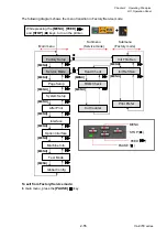
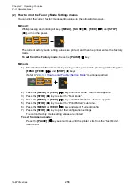
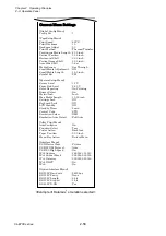
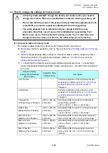
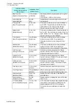
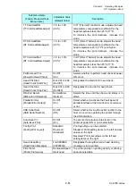
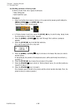
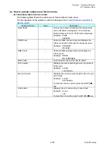
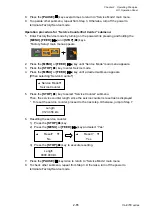
The following diagram shows the menu transition in Factory/Service mode.
To exit from Factory/Service mode:
In main menu, press the
[PAUSE]
( ) key.
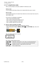
While pressing the
[MENU]
,
[FEED]
(
)
and
[STOP]
(
■
) keys, turn on the printer.
Factory Setup
Service Mode
[MENU]
Page Setup
System Setup
After Print
Interface
Machine Info
Test Mode
Global Config
Main menu
Init Thru Sen
Init Refl Sen
Submenu
(Factory mode)
Head Check
ROM Check
Cut Counter
Submenu
(Service mode)
Print Prefer
Option Interface
[MENU]
[
MENU]
[MENU]
[MENU]
[MENU]
[MENU]
[MENU]
[MENU]
PAUSE ( )
STOP (
■
)
FEED (
)
MENU
[MENU]
[MENU]
[MENU]
[MENU]
■
■
Summary of Contents for CL-E700 Series
Page 1: ...Technical Manual CL E700 series Thermal Transfer Printer...
Page 5: ...Chapter 1 Specifications 1 1 CL E700 series CHAPTER 1 SPECIFICATIONS...
Page 15: ...Chapter 2 Operating Principles 2 1 CL E700 series CHAPTER 2 OPERATING PRINCIPLES...
Page 87: ...Chapter 3 Disassembly and Maintenance 3 1 CL E700 series CHAPTER 3 DISASSEMBLY AND MAINTENANCE...
Page 151: ...Chapter 4 Troubleshooting 4 1 CL E700 series CHAPTER 4 TROUBLESHOOTING...
Page 167: ...Chapter 5 Parts Lists CL E700 series CHAPTER 5 PARTS LISTS...
Page 172: ...Chapter 5 Parts Lists CL E700 series 5 6 DRAWING NO 1 General Assembly Rev 0...
Page 195: ...Chapter 5 Parts Lists 5 29 CL E700 series DRAWING NO 7 Unit Opepane Rev 0...
Page 203: ...Chapter 5 Parts Lists 5 37 CL E700 series DRAWING NO 9 SA2 Ribbon Unit Fan Rev 0...
Page 206: ...Chapter 5 Parts Lists CL E700 series 5 40 DRAWING NO 10 Accessories Rev 0 3 2 4 1 1 1 2 1 3...
Page 208: ...Chapter 6 Circuit Diagrams 6 1 CL E700 series CHAPTER 6 CIRCUIT DIAGRAMS...
Page 230: ...Appendices AP 1 CL E700 series APPENDICES...
Page 233: ...Appendices A Mounting Diagrams CL E700 series AP 4 2 Solder side...

