Chapter 3 Disassembly and Maintenance
3-7. Adjustments
CL-E700 series
3-50
3-7.
Adjustments
3-7-1. Transparent/Reflective Sensor Adjustment
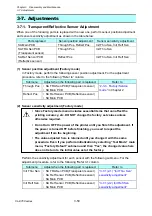
When one of the following parts is replaced with a new one, perform sensor position adjustment
and sensor sensitivity adjustment as shown in the table below.
Parts replaced
Sensor position adjustment
Sensor sensitivity adjustment
SA Main PCB
Through Pos, Reflect Pos
Init Thru Sen, Init Refl Sen
SA TRA Sen PCB
(Transparent sensor)
Through Pos
Init Thru Sen
SA Ref Sensor PCB
(Reflective sensor)
Reflect Pos
Init Thru Sen, Init Refl Sen
(1) Sensor position adjustment (Factory mode)
In Factory mode, perform the following sensor position adjustment. For the adjustment
procedure, refer to the following “Refer to” column.
Submenu
Adjust when the following part is replaced.
Refer to
Through Pos • SA TRA Sen PCB (Transparent sensor)
• SA Main PCB
Reflect Pos
• SA Ref Sensor PCB (Reflective sensor)
• SA Main PCB
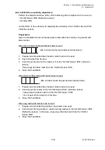
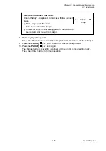
(2) Sensor sensitivity adjustment (Factory mode)
• Since Factory mode menu includes essential items that can affect the
printing accuracy, etc, DO NOT change the factory set values unless
otherwise required.
• Do not turn OFF the power of the printer until you finish the adjustment. If
the power is turned OFF before finishing, you need to repeat the
adjustment from the beginning.
• The value adjusted here is retained until you change it with the same
procedure. Even if you perform initialization by selecting “Test Mode” main
menu, “Factory Default” submenu and then “Yes”, the changed value here
does not return to the initial value set at the factory.
Perform the sensitivity adjustment for each sensor with the following submenu. For the
adjustment procedure, refer to the following “Refer to” column.
Submenu
Adjust when the following part is replaced.
Refer to
Init Thru Sen • SA TRA Sen PCB (Transparent sensor)
• SA Ref Sensor PCB (Reflective sensor)
• SA Main PCB
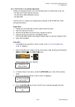
“3-7-1(2-1) “Init Thru Sen”
sensitivity adjustment”
Init Refl Sen
• SA Ref Sensor PCB (Reflective sensor)
• SA Main PCB
Summary of Contents for CL-E700 Series
Page 1: ...Technical Manual CL E700 series Thermal Transfer Printer...
Page 5: ...Chapter 1 Specifications 1 1 CL E700 series CHAPTER 1 SPECIFICATIONS...
Page 15: ...Chapter 2 Operating Principles 2 1 CL E700 series CHAPTER 2 OPERATING PRINCIPLES...
Page 87: ...Chapter 3 Disassembly and Maintenance 3 1 CL E700 series CHAPTER 3 DISASSEMBLY AND MAINTENANCE...
Page 151: ...Chapter 4 Troubleshooting 4 1 CL E700 series CHAPTER 4 TROUBLESHOOTING...
Page 167: ...Chapter 5 Parts Lists CL E700 series CHAPTER 5 PARTS LISTS...
Page 172: ...Chapter 5 Parts Lists CL E700 series 5 6 DRAWING NO 1 General Assembly Rev 0...
Page 195: ...Chapter 5 Parts Lists 5 29 CL E700 series DRAWING NO 7 Unit Opepane Rev 0...
Page 203: ...Chapter 5 Parts Lists 5 37 CL E700 series DRAWING NO 9 SA2 Ribbon Unit Fan Rev 0...
Page 206: ...Chapter 5 Parts Lists CL E700 series 5 40 DRAWING NO 10 Accessories Rev 0 3 2 4 1 1 1 2 1 3...
Page 208: ...Chapter 6 Circuit Diagrams 6 1 CL E700 series CHAPTER 6 CIRCUIT DIAGRAMS...
Page 230: ...Appendices AP 1 CL E700 series APPENDICES...
Page 233: ...Appendices A Mounting Diagrams CL E700 series AP 4 2 Solder side...

