Chapter 3 Disassembly and Maintenance
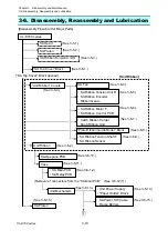
3-6. Disassembly, Reassembly and Lubrication
3-
13
CL-E700
series
3-6-2. Unit Ribbon
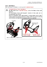
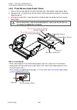
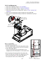
When removing the “Unit Ribbon”, do not loosen the “
Forbidden Screws
”.
“Forbidden Screws” in the “Unit Ribbon”
DO NOT loosen the 9
“Forbidden Screws”
of the “SA Ribbon Frame (with
Support)”.
The “SA Ribbon Frame (with Support)” consists of three parts and is
assembled with the 9 screws.
Once the “SA Ribbon Frame (with Support)” is disassembled, correct ribbon
running cannot be assured. Therefore, a ribbon wrinkle may not be removed
with the Ribbon Left-Right Balance Adjustment Knob, as expected.
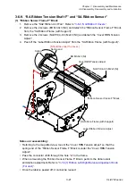
DO NOT LOOSEN.
Forbidden 4 Screws
SA Ribbon Frame
(with Support)
Ribbon Left-Right Balance Adjustment Knob
Unit Ribbon
Forbidden 5 Screws
DO NOT LOOSEN.
Summary of Contents for CL-E700 Series
Page 1: ...Technical Manual CL E700 series Thermal Transfer Printer...
Page 5: ...Chapter 1 Specifications 1 1 CL E700 series CHAPTER 1 SPECIFICATIONS...
Page 15: ...Chapter 2 Operating Principles 2 1 CL E700 series CHAPTER 2 OPERATING PRINCIPLES...
Page 87: ...Chapter 3 Disassembly and Maintenance 3 1 CL E700 series CHAPTER 3 DISASSEMBLY AND MAINTENANCE...
Page 151: ...Chapter 4 Troubleshooting 4 1 CL E700 series CHAPTER 4 TROUBLESHOOTING...
Page 167: ...Chapter 5 Parts Lists CL E700 series CHAPTER 5 PARTS LISTS...
Page 172: ...Chapter 5 Parts Lists CL E700 series 5 6 DRAWING NO 1 General Assembly Rev 0...
Page 195: ...Chapter 5 Parts Lists 5 29 CL E700 series DRAWING NO 7 Unit Opepane Rev 0...
Page 203: ...Chapter 5 Parts Lists 5 37 CL E700 series DRAWING NO 9 SA2 Ribbon Unit Fan Rev 0...
Page 206: ...Chapter 5 Parts Lists CL E700 series 5 40 DRAWING NO 10 Accessories Rev 0 3 2 4 1 1 1 2 1 3...
Page 208: ...Chapter 6 Circuit Diagrams 6 1 CL E700 series CHAPTER 6 CIRCUIT DIAGRAMS...
Page 230: ...Appendices AP 1 CL E700 series APPENDICES...
Page 233: ...Appendices A Mounting Diagrams CL E700 series AP 4 2 Solder side...

