background image

CL-S300 Series Service Manual 

- 15 - 

2-3.  Assembly Procedure 

When reassembling the parts, follow the procedure of 

“1-2 Disassembly Procedure” in reverse. 


Summary of Contents for CL-S300

Page 1: ...Service Manual Direct Thermal Barcode Label Printer CL S300 Series Revision 1 00 2015 6 10...

Page 2: ......

Page 3: ...ies Service Manual i REVISIONS Rev No Date Page Comment 1 00 2015 6 10 Newly issued CITIZEN is a registered trademark of CITIZEN HOLDINGS CO LTD Japan CITIZEN es una marca registrada de Citizen Holdin...

Page 4: ...ND REASSEMBLY 2 2 1 Tools Used 2 2 2 Disassembly Procedure 3 1 SA HEAD 1 SP 300 PPM80012 00 3 2 SA MAIN PCB SP 300 PPS00171 00 5 3 SA MOTOR SP 300 PPF80006 00 8 4 SA PLATEN SP 300 PPK90015 00 10 5 SA...

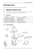
Page 5: ...hased this product 1 1 Parts List Part Number Part Name Description 1 PPM80012 00 SA HEAD 1 SP 300 TPH 203dpi module CL S300 2 PPS00171 00 SA MAIN PCB SP 300 Main board assembly module CL S300 3 PPF80...

Page 6: ...ing inspection perform a check to ensure that there is no irregularity before turning on the printer Use caution not to leave any part or screw used for maintenance inside of the printer When handling...

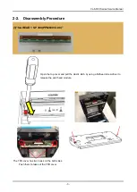
Page 7: ...sembly Procedure 1 SA HEAD 1 SP 300 PPM80012 00 Open the top cover and pull the plastic latch by using a flathead screw driver to release the print head module The TPH cover has two hooks on the both...

Page 8: ...the TPH and unplug the TPH connector Put on gloves and do not touch the TPH with bare hands when handling Note that the connector joint is very soft and vulnerable Hold the connector plastic when hand...

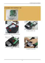
Page 9: ...300 Series Service Manual 5 2 SA MAIN PCB SP 300 PPS00171 00 Unscrew and take out 4 screws on the bottom cover Remove the bottom cover Unscrew the screw which holds the main PCB Unplug the AC power ca...

Page 10: ...C adapter Unplug the connectors from the main PCB Unscrew the screw which holds the motor to remove the ESD cable Take out the plastic covers on the both sides of the platen roller by using a flat hea...

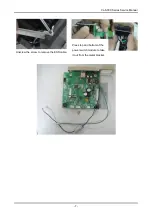
Page 11: ...CL S300 Series Service Manual 7 Unscrew the screw to remove the ESD cable Press top and bottom of the power switch module to take it out from the metal bracket...

Page 12: ...S300 Series Service Manual 8 3 SA MOTOR SP 300 PPF80006 00 Unscrew and take out 4 screws on the bottom cover Remove the bottom cover Unscrew the screw which holds the main PCB Unplug the AC power cab...

Page 13: ...s Service Manual 9 Lift up the main PCB and the AC adapter Unplug the connectors from the main PCB Unscrew the screw which holds the motor to remove the ESD cable Unscrew another screw to take out the...

Page 14: ...ies Service Manual 10 4 SA PLATEN SP 300 PPK90015 00 Take out the plastic covers on the both sides of the platen roller by using a flat head screwdriver Lift up the platen roller by using a flat head...

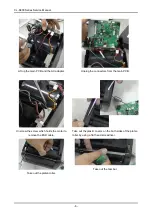
Page 15: ...300 PPS00172 00 Unscrew to open the bottom cover Lift up the AC adapter Unplug the connector for the label sensor from the main PCB The label sensor is held with a plastic ring by two hooks Press two...

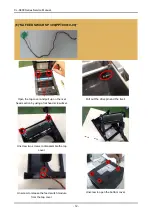
Page 16: ...Open the top cover and pull up on the rivet head section by using a flat head screwdriver Pull out the drive pin and the rivet Unscrew two screws to disassemble the top cover Unscrew to release the fe...

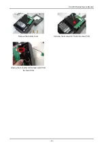
Page 17: ...CL S300 Series Service Manual 13 Remove the bottom cover Unscrew the screw which holds the main PCB Unplug the connector for the feed switch from the main PCB...

Page 18: ...eries Service Manual 14 7 SA PEELER SP 300 PZN10001 00 Unscrew to open the bottom cover Lift up the AC adapter Unscrew the two screws which hold the peeler Unplug the connector for the peeler from the...

Page 19: ...CL S300 Series Service Manual 15 2 3 Assembly Procedure When reassembling the parts follow the procedure of 1 2 Disassembly Procedure in reverse...

Reviews: