3-5. Disassembly, Reassembly and Lubrication
3-29
CLP-621 & CLP-631
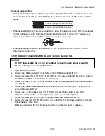
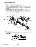
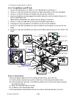
• When assembling the Head Up Spring (thin) and the Head Up Spring 2 (thick), first, hook them
on the upper arms (Head Block), and then on the lower arms (PF Unit).
In this case, hook the Head Up Spring so that its opening ends come outward as shown in the
figure. (This can prevent unwanted noise generation produced when the Head Block is opened
or closed, though this phenomenon rarely happens.)
Open ends of the
Head Up Spring
Spring 2, Head Up
Spring, Head Up
Thin
Thick
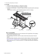
• When tying the Wire Tie on the lower side (not the Wire Tie on the upper side), wind it so that the
flat surface is inside. (This prevents the cable from being rubbed by the uneven (not flat) surface
when the Head Block is opened or closed.)
(Flat)
(Not flat)
Cable
Summary of Contents for CLP-621
Page 1: ...Technical Manual CLP 621 CLP 631 Thermal Transfer Barcode Label Printer JM74961 00F 1 00E 0701...
Page 2: ...CLP 621 CLP 631 ii Copyright 2007 by CITIZEN SYSTEMS JAPAN CO LTD...
Page 4: ...CHAPTER 1 SPECIFICATIONS CLP 621 CLP 631...
Page 13: ...CHAPTER 2 OPERATING PRINCIPLES CLP 621 CLP 631...
Page 73: ...CHAPTER 3 DISASSEMBLY AND MAINTENANCE CLP 621 CLP 631...
Page 126: ...CLP 621 CLP 631 CHAPTER 4 TROUBLESHOOTING...
Page 138: ...CLP 621 CLP 631 CHAPTER 5 PARTS LISTS...
Page 166: ...Chapter 5 Parts Lists CLP 621 CLP 631 5 29 DRAWING NO 7 Control Panel Unit Rev 0 4 3 2 1 5...
Page 177: ...Chapter 5 Parts Lists CLP 621 CLP 631 5 40 DRAWING NO 10 Accessories Rev 0 3 2 4 1...
Page 179: ...CHAPTER 6 CIRCUIT DIAGRAMS CLP 621 CLP 631...
Page 208: ...APPENDICES CLP 621 CLP 631...
Page 212: ...B Mounting Diagrams AP 5 CLP 621 CLP 631 Main PCB Solder side...
Page 214: ...B Mounting Diagrams AP 7 CLP 621 CLP 631 B 3 Ribbon Main PCB Parts side Solder side...
Page 217: ......


