3-6. Adjustments
3-43
CLP-621 & CLP-631
3-43
CLP-621 & CLP-631
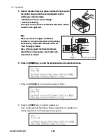
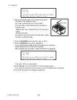
When adjustment is successful, “Finished DAC XXX” is displayed.
When adjustment is successful, “Finished DAC XXX” is displayed.
*The value “143” is one of samples.
9. Press
any
key
on the control panel to store the adjusted value.
Proceed to step 10 to perform reflective sensor adjustment.
[When adjustment failed]
When adjustment failed, “Cannot Setup” is displayed.
1) Press any key on the control panel to return to the screen in step 4.
2) Check the mechanical sensor positions, current Media sensor menu setting, label
paper, etc. and try again.
[Reflective sensor sensitivity adjustment, Media: Tag]
10. Press the [PAUSE] key to select the reflective sensor menu.
“Ini Refl Sensor” screen will appear.
[PAUSE]
key
11. Press the [FEED] key to enter the reflective sensor menu.
Summary of Contents for CLP-621
Page 1: ...Technical Manual CLP 621 CLP 631 Thermal Transfer Barcode Label Printer JM74961 00F 1 00E 0701...
Page 2: ...CLP 621 CLP 631 ii Copyright 2007 by CITIZEN SYSTEMS JAPAN CO LTD...
Page 4: ...CHAPTER 1 SPECIFICATIONS CLP 621 CLP 631...
Page 13: ...CHAPTER 2 OPERATING PRINCIPLES CLP 621 CLP 631...
Page 73: ...CHAPTER 3 DISASSEMBLY AND MAINTENANCE CLP 621 CLP 631...
Page 126: ...CLP 621 CLP 631 CHAPTER 4 TROUBLESHOOTING...
Page 138: ...CLP 621 CLP 631 CHAPTER 5 PARTS LISTS...
Page 166: ...Chapter 5 Parts Lists CLP 621 CLP 631 5 29 DRAWING NO 7 Control Panel Unit Rev 0 4 3 2 1 5...
Page 177: ...Chapter 5 Parts Lists CLP 621 CLP 631 5 40 DRAWING NO 10 Accessories Rev 0 3 2 4 1...
Page 179: ...CHAPTER 6 CIRCUIT DIAGRAMS CLP 621 CLP 631...
Page 208: ...APPENDICES CLP 621 CLP 631...
Page 212: ...B Mounting Diagrams AP 5 CLP 621 CLP 631 Main PCB Solder side...
Page 214: ...B Mounting Diagrams AP 7 CLP 621 CLP 631 B 3 Ribbon Main PCB Parts side Solder side...
Page 217: ......


