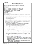
3-6. Adjustments
CLP-621 & CLP-631
3-48
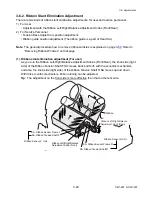
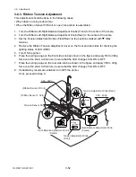
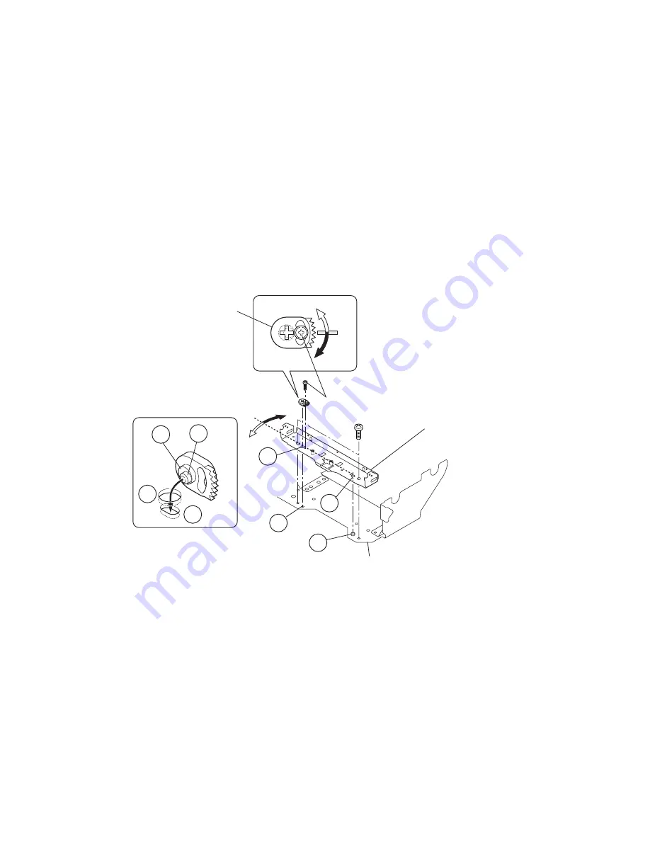
Principle of operation of parallelism change with the Tension Base Adjust Cam:
The parallelism of the Ribbon Sensor F/R Unit can be changed by means of the eccentric
mechanism of the Tension Base Adjust Cam.
The Tension Base Adjust Cam has projections “
a
” and “
b
”. The projection “
a
” is inserted
into the slotted hole “
a’
” on the base (fixed part), while the projection “
b
” is inserted into
the hole “
b’
” on the Ribbon Tension Frame F/R SA of the Ribbon Sensor F/R Unit
(movable part).
As you can see from the figure, the projection “
a
” is eccentric with respect to the projection
“
b
”. Accordingly, as your turn the Tension Base Adjust Cam (after loosening screws “
A
” (2
pcs.) and “
B
”), the eccentric projection “
a
” pushes the slotted hole
“
a’
“ so that the Ribbon
Sensor F/R Unit itself turns around the supporting point “
c
”. (The Ribbon Sensor F/R Unit
turns in the same direction as you turn the Tension Base Adjust Cam.)
[In the case of front side]
A
B
a
a’
b’
c
c’
b
a’
b’
SA, Ribbon Tension Frame F
(movable part)
Tension Base
Adjust Cam
SA1, Ribbon Unit Base Plate (fixed part)
Summary of Contents for CLP-621
Page 1: ...Technical Manual CLP 621 CLP 631 Thermal Transfer Barcode Label Printer JM74961 00F 1 00E 0701...
Page 2: ...CLP 621 CLP 631 ii Copyright 2007 by CITIZEN SYSTEMS JAPAN CO LTD...
Page 4: ...CHAPTER 1 SPECIFICATIONS CLP 621 CLP 631...
Page 13: ...CHAPTER 2 OPERATING PRINCIPLES CLP 621 CLP 631...
Page 73: ...CHAPTER 3 DISASSEMBLY AND MAINTENANCE CLP 621 CLP 631...
Page 126: ...CLP 621 CLP 631 CHAPTER 4 TROUBLESHOOTING...
Page 138: ...CLP 621 CLP 631 CHAPTER 5 PARTS LISTS...
Page 166: ...Chapter 5 Parts Lists CLP 621 CLP 631 5 29 DRAWING NO 7 Control Panel Unit Rev 0 4 3 2 1 5...
Page 177: ...Chapter 5 Parts Lists CLP 621 CLP 631 5 40 DRAWING NO 10 Accessories Rev 0 3 2 4 1...
Page 179: ...CHAPTER 6 CIRCUIT DIAGRAMS CLP 621 CLP 631...
Page 208: ...APPENDICES CLP 621 CLP 631...
Page 212: ...B Mounting Diagrams AP 5 CLP 621 CLP 631 Main PCB Solder side...
Page 214: ...B Mounting Diagrams AP 7 CLP 621 CLP 631 B 3 Ribbon Main PCB Parts side Solder side...
Page 217: ......


