background image

Chapter 5. Parts Lists 

CLP-621 & CLP-631


5-5 


CLP-621 & CLP-631 


 Drawing 

No. 


Parts List & Location for General Assembly 

Revision Up List 

Sheet No. Rev. No.

Date 

1/1 

Dec. 20, 2006


Summary of Contents for CLP-621

Page 1: ...Technical Manual CLP 621 CLP 631 Thermal Transfer Barcode Label Printer JM74961 00F 1 00E 0701...

Page 2: ...CLP 621 CLP 631 ii Copyright 2007 by CITIZEN SYSTEMS JAPAN CO LTD...

Page 3: ...CHAPTER 1 SPECIFICATIONS CHAPTER 2 OPERATING PRINCIPLE CHAPTER 3 DISASSEMBLY AND MAINTENANCE CHAPTER 4 TROUBLESHOOTING CHAPTER 5 PARTS LISTS CHAPTER 6 CIRCUIT DIAGRAMS APPENDICES iii CLP 621 CLP 631...

Page 4: ...CHAPTER 1 SPECIFICATIONS CLP 621 CLP 631...

Page 5: ...CHAPTER 1 SPECIFICATIONS TABLE OF CONTENTS 1 1 General Specifications 1 3 1 2 Printable Area 1 7 1 3 Printing Position Accuracy 1 8 1 4 Adjustable Sensors 1 9 CLP 621 CLP 631 1 2...

Page 6: ...after printing is completed Cut mode 1 Prints while cutting at designated sheet units The following two kinds of cut mode operations are available Back feed Cut through Cut through refers to stopping...

Page 7: ...bon length 360 0 m 1 181 ft Max roll diameter 74 0 mm 2 90 Inner diameter of the paper tube 25 4 0 25 mm 1 00 0 01 Ribbon end detection Ribbon out detection by a tension sensor Bar code One dimension...

Page 8: ...cts media gap between labels notches on tags and media out Reflective sensor Detects reflective mark on back of media and media out Label peeling sensor 1 Communication interfaces Parallel IEEE1284 Co...

Page 9: ...itions Operating temp 5 to 35 C humidity 30 to 80 condensation free Conditions ventilation and natural convection Storage temperature conditions Temp 20 to 60 C humidity 5 to 85 Conditions ventilation...

Page 10: ...ia width is 118 mm 4 65 there are unprintable areas on both sides 2 5 mm 0 10 width is on the left side and 11 5 mm 0 45 for CLP 621 10 5 mm 0 41 for CLP 631 width on the right side The left side unpr...

Page 11: ...on as follows 1 2 mm 2 0 04 0 08 Reference edge Paper guide Printable area Direction of media feed Ideal printing start position Actual printing start position 1 2 5 1 mm 3 0 10 0 04 100 2 mm 4 39 4 0...

Page 12: ...end The mechanical adjustable range of both sensors is equal and they are adjustable independently When both sensors are moved to the left end or the right end center of the printing mechanism both se...

Page 13: ...CHAPTER 2 OPERATING PRINCIPLES CLP 621 CLP 631...

Page 14: ...2 16 1 Filter power supply section 2 16 2 Main PCB 2 16 3 Operation panel 2 16 4 Thermal print head 2 17 5 Sensors 2 17 6 Motor 2 17 7 Parallel I F IEEE1284 2 17 8 Serial I F RS 232C 2 17 9 USB Univer...

Page 15: ...2 4 Interface 2 49 2 4 1 Serial Interface 2 49 1 Specifications 2 49 2 Signal line and pin assignment 2 49 3 Protocol 2 50 2 4 2 Parallel Interface 2 51 1 Specifications 2 51 2 Signal line and pin ass...

Page 16: ...it section Part name Description Ribbon Motor F Front side This motor takes up ribbon A thermistor is attached to the side surface of this motor to detect the motor temperature Ribbon Motor R Rear sid...

Page 17: ...or This sensor is a photo sensor to detect the labels stuck on liner or U shaped notches on tag It also detects the media end Reflective Sensor Bottom sensor This sensor is a photo sensor to detect th...

Page 18: ...e viewing from the right side of the printer the Platen SA turns counterclockwise via the gear train PF1 Gear PF2 Gear and PF Idle Gear and media is fed forward by the friction force produced between...

Page 19: ...labels on liner or U shaped notches of tag Both reflective and transparent sensors are used to detect the media end Aligning the sensors for label paper or tag with U shaped notches For label paper b...

Page 20: ...enu See Through For detecting U shaped notches of tag both reflective sensor and transparent sensor are used The U shaped notches are detected in the same way as the label mentioned above except that...

Page 21: ...s detected by the reflective sensor LED light amount control According to the media selected by the Media Sensor menu See Through Reflect or None the amount of light is well controlled to detect the l...

Page 22: ...bon On the supply side the Ribbon Motor R turns to supply ribbon while applying adequate back tension to ribbon to eliminate ribbon slack On the supply side the rotational direction of the Ribbon Moto...

Page 23: ...Ribbon Gears 1 2 3 and 4 and ribbon is taken up On the supply side the rotational direction of the Ribbon Motor R differs depending on the ribbon winding type to be used In the case of the outside wou...

Page 24: ...to turn to take up ribbon Then the claw C is inserted into the photointerrupter again and the Ribbon Motor F stops This cycle is repeated and constant tension is applied to ribbon On the supply side...

Page 25: ...ed from the head up sensor At this time the head up sensor turns ON and Low level is output from the head up sensor While the head block is in the down position the protrusion A is engaged in the head...

Page 26: ...d SA will slant to the right resulting in uneven printing density The part A of the Head Balance Lever is pushed against the cam part by the Head R Spring and it moves up step by step as the media wid...

Page 27: ...ion of the thermal elements will shift toward the left a little from the center of the Platen SA viewing from the right side of the Platen SA As the optimum position varies according to the hardness o...

Page 28: ...IEEE1284 Parallel I F Ethernet I F PCB Wireless LAN I F PCB Option Ribbon Motor F R Ribbon Main PCB Tension Sensor F R Major functions of individual components are described below 1 Filter power suppl...

Page 29: ...epping motor to feed media The Ribbon Motor F and Ribbon Motor R are stepping motors to take up and supply ribbon respectively 7 Parallel I F IEEE1284 This is the parallel I F to transmit and receive...

Page 30: ...otor PF Motor Driver Ribbon Motor Drivers Transparent Sensor Thermal Print Head Gate Array UPD65946GJ 165 3EB A Operation Panel RS232C IEEE1284 USB 1 1 MAIN PCB Peeler Sensor Option Peeler Thermal Hea...

Page 31: ...ncorporates a control circuit for the interface I O port motors print head etc e Head control This is a circuit to control the thermal head driver incorporated in the thermal head It also checks if a...

Page 32: ...Custom IC 4000000H 40FFFFFH SDRAM 0800000H 8M bytes 0FFFFFFH CPU FFFB000H FFFEFFFH FFFF000H FFFFFFFH CPU Boot Loader 1 Setting Information User Settings Setting Information Factory set Settings Boot L...

Page 33: ...nd pin 117 HDUSENS of IC1 CPU goes to High level When the head block is opened in the up position the protrusion A is disengaged from the head up sensor and the light emitted from the LED reaches the...

Page 34: ...oltage corresponding to the amount of light is applied to pin 5 TRANMON of IC1 CPU Meanwhile when the liner with the label stuck on it passes between both sensors the light is blocked by the label and...

Page 35: ...the LEDs the operation is the same as for the transparent sensor 5V Media Transparent Sensor Main PCB Reflective Sensor 3 2 3 4 1 4 5 CN7 2 1 Transparent Sensor PCB Reflective Sensor PCB IC4 D A Conve...

Page 36: ...ks the claw of the Ribbon Tension Shaft F SA comes off the photointerrupter and the photointerrupter turns ON The LED goes out when ribbon tightens If ribbon is not correctly fed during printing the O...

Page 37: ...ording to the temperature change the voltage at pin 7 HDTMP of IC1 CPU changes accordingly The CPU senses the voltage at pin 7 to detect the head temperature According to the temperature of the print...

Page 38: ...3A uPD271G2 2 3 7 5V 3 3V R163 R167 R166 R165 R162 R161 Printing operation at PF motor temperature rise When the temperature of the PF motor rises above 95 C 203 F printing speed is reduced to avoid o...

Page 39: ...voltage at pin 11 to detect the ribbon motor temperature 5 CN702 M Ribbon Motor F Take up Side 6 Thermistor R113 C73 IC1 CPU Ribbon Main PCB ENVTMP ANI6 11 9 CN701 20 3 3V 1 12 CN8 Main PCB Printing...

Page 40: ...o the PF Motor is shut off For TEMPOFF signal refer to 3 5 PF motor temperature sensor TEMPOFF signal is normally at High level and the output from IC12 can turn ON TR3 to supply 24V to the PF Motor I...

Page 41: ...on to be used inside wound ink in ribbon or outside wound ink out ribbon The output of the Ribbon Winding Selection Switch is connected to IC702 and by combining this output signal with the DIR_B sign...

Page 42: ...the thermal elements to print dots on thermal transfer paper The width of heating pulse will be changed according to the head temperature to keep the printing density constant According to the print d...

Page 43: ...r checking where TR2 turns ON and a thermal element R is selected At the point A the voltage divided by R77 and R is developed The CPU monitors this voltage at pin 10 HEADRES and check if the voltage...

Page 44: ...perature falls under 70 C 158 F 130 FANCTL IC1 CPU D30 1 R130 R131 TR5 2SK3577 Main PCB CN8 11 1 CN21 D701 5V 5V 19 5V FANOUT 1 2 F702 Fan CN706 Ribbon Motor Fan CN701 Ribbon Main PCB 5 Other circuits...

Page 45: ...Reset 26 IC1 CPU RESET IC11 Custom IC Power ON Reset 3 3V RESET 3 3V H L 0V P52 GRESET GRESET Pin 1 of IC3 IC3 BD5328FVE P17 C3 T4 RESET Vout CT SUB 2 VDD 5 28 23 C4 5 3 Clock circuit Crystal oscillat...

Page 46: ...02 SW303 SW304 SW301 D301 To From IC11 Custom IC 5 5 USB I F control circuit The USB control circuit interfaces with the USB Universal Serial Bus NAND gates IC19 and transistor DTR5 consist of a USB c...

Page 47: ...D and STOP The function name on the key is selected when the key is pressed 2 LEDs There are 4 LEDs POWER PRINT CONDITION and ERROR The LEDs light up or blink to indicate printer status setting modes...

Page 48: ...ED STOP POWER Enters sensor adjustment mode See 1 1 For details see the User s Manual MODE POWER Enters menu setting mode See 1 2 For details see the User s Manual 1 1 Sensor adjustment mode According...

Page 49: ...ion 0 00 inch Horizontal Shift 0 00 inch Horizontal Shift 0 00 inch Media Sensor See Through Media Sensor See Through Small Media Adjustment Off Small Media Adjustment Off Small Media Length 1 00 inch...

Page 50: ...sing and holding the FEED key turn on the power 2 When the PRINT LED blinks slowly later it will blink rapidly release the FEED key The printer enters self print mode The label is fed self test printi...

Page 51: ...The PRINT LED will blink slowly When it changes to rapid blink release the STOP key The printer enters hex dump mode and hex dump printing starts To exit hex dump mode turn off the power DUMP LIST 02...

Page 52: ...e menu appears at the top of the user menus as follows PAUSE STOP FEED MODE REPEAT No Next item Increase item Yes Select Save Next digit Exit the current menu or the VuePrint menu system The menu oper...

Page 53: ...Current Menu Settings Current Menu Settings Page Setup Menu Page Setup Menu Print Speed 4 IPS Print Speed 4 IPS Print Darkness 10 Print Darkness 10 Darkness Adjust 00 Darkness Adjust 00 Print Method...

Page 54: ...the STOP key See step 7 To return to the previous one press the MODE key To return to the previous one press the MODE key 6 Press the PAUSE key to enter the submenus 6 Press the PAUSE key to enter th...

Page 55: ...on page 2 46 Mach Cut Position 000 Save PAUSE Next Digit FEED Change value STOP Exit MODE Mach Peel Position 000 Save PAUSE Next Digit FEED Change value STOP Exit MODE Mach Hor Pos 08 Save PAUSE Next...

Page 56: ...6 Machine Cut Position 256 to 256 dots 000 dots Logically shifts the cutting position back and forth 32 to 32 mm 1 26 to 1 26 Optional Machine Peel Position 256 to 256 dots 000 dots Logically shifts t...

Page 57: ...enu Name Adjustable Value Default Value Description Double Heat ON OFF OFF Prints the same dot twice PowerOn Head Check ON OFF ON Enables the head check at power ON Ribbon End Detection Quick Normal S...

Page 58: ...the STOP key once to specify 1 Each time you press the key the value of the current digit with the cursor will scroll 0 1 2 3 4 9 0 4 Next press the FEED key to move the cursor to the next digit 18 T...

Page 59: ...Nothing is printed RAM Check None PAUSE Performs RAM capacity check and prints the check result Example RAM OK 16384K STOP Nothing is printed Cutter Check None PAUSE Performs cutter operation check o...

Page 60: ...he Factory Service Mode 2 Press the PAUSE key until Head Check submenu is printed 3 Press the PAUSE key to check for head abnormality The number of faulty thermal elements is printed Example Bad head...

Page 61: ...nal name Function 1 FG Frame ground Protective grounding 2 TXD Transmit Data Signal line that transmits data from the printer to the host 3 RXD Receive data Signal line that transmits data from the ho...

Page 62: ...turned from on line to off line When the media end is detected When a printer error occurs X ON code sending X OFF code sending 16K bytes 1024 bytes 128 bytes Received data 0 16K READY BUSY System DT...

Page 63: ...hannel ECP mode ECP mode permits bi directional asynchronous data transmission and by means of interlock handshake it does not require the timing necessary with Compatible mode Signal level IEEE1284 c...

Page 64: ...Compatible mode Paper end Busy PError Select Fault L H L H H L H L Error other than paper end Head open Other Busy PError Select Fault L H L unchanged H L H L Conditions for Busy Receive buffer full D...

Page 65: ...obe and data is latched at the leading edge of Strobe While receiving PRIME signal Note If the PRIME signal width is 10 sec or less it is not accepted BUSY goes to High when the PRIME signal is accept...

Page 66: ...versal Serial Bus Specification Transmission speed Compatible with 12Mbps full speed transmission Receive buffer 16K bytes Connector DUSB DUSB BRA42 T11 DDK 2 Signal line and pin arrangement Pin No Si...

Page 67: ...type or 220 240V AC type 2 5 1 Block diagram The following shows a block diagram for this power supply For the circuit corresponding blocks A to E refer to the circuit diagram on the following pages...

Page 68: ...2 5 Power Supply CLP 621 CLP 631 2 56 N1 N2 N3 N4 BLOCK A BLOCK E BLOCK B BLOCK C BLOCK D 120V type...

Page 69: ...2 5 Power Supply 2 57 CLP 621 CLP 631 N1 N2 N3 N4 Block A Block B Block C Block E Block D 220 240V type...

Page 70: ...e is 115V AC This DC voltage is supplied to the next converter and driver circuit For 200 240V type Full wave rectification is performed by the bridge rectifier DS1 and the capacitors C5 1 and C5 2 Th...

Page 71: ...ltage is produced there When the voltage at pin 6 VCC reaches approx 16V DC IC1 is activated and a pulse is output from pin 5 OUT of IC1 to drive Q1 When Q1 starts switching approx 20 25V DC is suppli...

Page 72: ...ed by R23 R22 R21 and C11 and input to pin 3 IS of IC1 If the voltage at pin 3 IS exceeds the internal reference voltage 0 24V of IC1 the switching pulse sent from pin 5 OUT is cut off resulting in lo...

Page 73: ...CHAPTER 3 DISASSEMBLY AND MAINTENANCE CLP 621 CLP 631...

Page 74: ...Sensor SA 3 17 3 5 10 Main PCB Block Power Supply Unit and Control Panel Unit 3 19 3 5 11 Main PCB Unit and Centro PCB Unit 3 21 3 5 12 Ope Pane PCB SA 3 21 3 5 13 Mechanism Unit and Case L 3 22 3 5 1...

Page 75: ...n slant elimination adjustment for user FRONT 3 46 1 2 Ribbon slant elimination adjustment for user REAR 3 46 2 Ribbon slant elimination adjustment For service personnel 3 47 2 1 Tension base adjust c...

Page 76: ...cularly do not loosen screws on any component unless necessary 2 After completing an inspection and before turning on the power be sure to check that there is no abnormality 3 Never try to print witho...

Page 77: ...ing Cleaning frequency Every 6 months or 300 hours of operation Whichever comes first Materials Dry cloth gauze or soft cloth and thermal head cleaner 3 3 Lubrication 1 Lubrication frequency This is a...

Page 78: ...r SA etc Maintenance Tools List No Name Q ty Description Remarks 1 Phillips Screwdriver Length 200 mm 1 For 3 4 mm screws 2 Phillips Screwdriver Length 100 mm 1 For 2 3 mm screws 3 Flat blade Screwdri...

Page 79: ...t ribbon running cannot be assured Namely ribbon slant correction may become impossible within the adjustable range of the Ribbon Left Right Balance Adjustment Knobs Front Rear Ribbon Left Right Balan...

Page 80: ...and detach the Ribbon Unit Fan SA2 Block and then disconnect 1 connector CN706 from the Ribbon Main PCB 3 Remove 4 screws PH N M3x4 and detach the Ribbon Unit Cover R 4 Remove 1 screw PH M3x3 and deta...

Page 81: ...BH N M3x6 and 1 nut M3 and detach the Top Cover Damper from the Case U upwardly Damper Top Cover BH N M3x6 Case U 621 Nut M3 NI Label FCC ICES Cover Front Notes on reassembling The Case U Cap cannot...

Page 82: ...move ribbon wrinkle 1 Remove the Top Cover SA Refer to 3 5 1 Top Cover SA 2 Remove 2 screws PH M3x6 and detach the Ribbon Unit by lifting it upward At this time disconnect 1 connector CN701 from the R...

Page 83: ...nd detach the two Ribbon Fan Brackets 3 Remove 2 screws BHT 2 M3x6 NI and detach the Fan Dir SW SA and the Ribbon Direction Knob from the Ribbon Unit Cover L Bracket Ribbon Fan Knob Ribbon Direction B...

Page 84: ...ribbon supply side remove 1 screw No 0 TFH M2x3 NI and 1 Ribbon Washer Plate Then remove the Holder R Shaft SA Ribbon Return Spring and Ribbon Gear 5R in that order 5 Also on the rear side disengage...

Page 85: ...remove the Ribbon Unit Fan SA2 Refer to Step 2 Normal way in 3 5 2 1 Removing the Case U without detaching the Ribbon Unit Normal way 2 Disconnect 1 connector CN701 from the Ribbon Main PCB 3 Remove...

Page 86: ...tighten screws while pushing the motor toward the Ribbon Gear 1 Front Gear 1 Ribbon 3 5 6 Ribbon Holder Catch and Ribbon Unit Knob 1 Open the Top Cover SA 2 Remove 4 screws BH M3x3 NI and detach the 2...

Page 87: ...r SA 2 Remove 4 screws NO 0 TFH M2x3 NI and detach the Ribbon Tension Adjust Covers on the front and rear sides 3 Remove 2 screws BH M3x3 NI and detach the Ribbon Sensor F Unit 4 Remove 2 screws BH M3...

Page 88: ...on Sub Adjust Lever F SA and Ribbon Tension Spring F 2 pcs from the Tension Adjust Lever F SA 7 Remove the tension adjust screw PH M1 7x4 from the Tension Adjust Lever F SA Note Do not remove this ten...

Page 89: ...DO NOT disassemble the Tension Base Adjust Cam and tension adjust screw PH M1 7x4 unless you need to replace them 1 Open the Top Cover SA 2 Remove the Ribbon Sensor R Unit Refer to 3 5 7 Ribbon Sensor...

Page 90: ...mbling Distinguish the Ribbon Tension Spring R used here from the Ribbon Tension Spring F used in 3 5 8 Ribbon Tension Shaft F SA They look like the same but the number of turns differs 18 turns Sprin...

Page 91: ...PCB To Ribbon Main PCB on the Ribbon Unit To Ribbon Main PCB on the Ribbon Unit Front 3 Remove 4 screws PHT BH2T M3x8 1 screw BH M4x4 NI and 1 washer EXT T 4 NI and then detach the Main PCB Block upwa...

Page 92: ...embling When running the Ope pane Cable pass it inner side of the case arms A When connecting the flexible cables be sure that the insertion direction is correct If you insert it reversely circuit is...

Page 93: ...PCB Unit and the Main PCB Sheet from the Main PCB Plate Plate Main PCB PHT ST 3 M3x5 BHT ST M3x5 Lock Screw SA Centro Cable Unit Main PCB Unit Centro PCB EXT T 3 NI Sheet Main PCB Sheet 2 Main PCB No...

Page 94: ...Earth L Sheet Earth R Sheet Earth Plate and 2 nuts M4 5 Remove the Ope pane Cover Cushion from the Case L The Ope pane Cover Cushion is not reusable 6 Remove the Case L F Legs and Case L R Legs from...

Page 95: ...B Block refer to 3 5 10 Main PCB Block Main PCB Block Head Wire Cover Media Guide End Unit Mechanism Align 3 5 14 Platen SA 1 Open the Top Cover SA and then the Head Block 2 While pushing the part A o...

Page 96: ...e Sensor U Unit Unit Sensor U C Approx 2 5 cm 1 When the Head Block is fully raised A B Head Block C PH M2x4 Notes on reassembling When assembling the Sensor U Unit be sure that the protrusions A and...

Page 97: ...Up Sensor Cable SA 3 Remove 1 screw NO 0 PHT BT 1 M2x3 and detach the Transparent Sensor PCB SA by disconnecting the Transparent Sensor Cable SA SA Transparent Sensor Cable SA Head Up Sensor PCB SA H...

Page 98: ...crews PH M2 6x3 i and detach the Sensor Frame L Cap j 7 Remove the Sensor U Holder k by sliding it to the right and detach the Transparent Sensor Cable SA 8 Remove the Sensor L Damper from the Sensor...

Page 99: ...s securely SA Transparent Sensor Cable Cap Sensor Cable U Tape Sensor Cable U D Fixing the spring Shorter slit Spring Sensor Frame Cap Sensor Frame L Cover Head Wire Sensor U Hoder body Cable for pull...

Page 100: ...from the PF Unit Block 8 Remove 1 screw BH N M3x6 and remove the Head Up Spring 2 Hook 8 from the PF Unit Block Lower side Wire Tie Flat side 5Shaft Head Holder 6Head Block 3Spring Head Up 4Spring2 H...

Page 101: ...ward as shown in the figure This can prevent unwanted noise generation produced when the Head Block is opened or closed though this phenomenon rarely happens Open ends of the Head Up Spring Spring 2 H...

Page 102: ...2 Remove the Head Block Refer to 3 5 17 Head Block and PF Unit 3 Place the Head Block upside down as shown in the figure 4 Remove 2 screws PH M3x6 and detach the Head Cable Guide 5 Set the media widt...

Page 103: ...gure d In this position the screw B of the Head Unit can be correctly inserted into the slit C of the frame If the screw B is not inserted into the slit C the Head Unit cannot be correctly seated 3 Wh...

Page 104: ...Head E Label Part Number White Label for CLP 621 Yellow Label for CLP 631 BH N M3x6 Notes on reassembling When assembling the Head SA insert its 2 protrusions into the guide holes E for aligning and...

Page 105: ...the Head SA without disassembling the Head Unit Though the normal disassembly procedure is described in 1 Head Unit on page 3 30 1 Raise the head block The following figure omits the Ribbon Unit 2 Dis...

Page 106: ...Head Adjust Shim s may be inserted for adjusting height depending on the printer to be used It may be inserted at the factory to obtain correct adjustable range of the Media Thickness Adjustment Dial...

Page 107: ...Sensor Cable SA from the bottom disconnect it from the Reflective Sensor PCB SA 3 Open the Head Block remove 1 screw PH M3x6 and detach the Guide Sensor L Holder 4 Slide the Paper Set Guide to the lef...

Page 108: ...djustment Refer to 3 6 1 Transparent Reflective Sensor Position Adjustment on page 3 40 Apply Floil G 311S along the groove of the frame as shown When assembling the Sensor L Damper push it so that th...

Page 109: ...ve the Motor SA Refer to 3 5 20 Motor SA Tip You can remove the gears without removing the PF Unit and the Motor SA 4 Pull out the PF2 Gear by releasing its lock and then pull out the PF1 Gear and the...

Page 110: ...Disengage 1 E Ring and detach the Head Lock Lever and the Head Lock Spring from the Main Plate R SA BH N M3x6 PH M3x6 E Ring 2 5 Lever Head Lock Spring Head Lock EXT T 3 NI SA Main Plate R Note on re...

Page 111: ...ew BH N M3x6 and 1 washer EXT T 3 NI and detach the Plate Peeler SA from the Main Plate L SA Frame Main SA Main Plate L BH N M3x6 NO 0 PH 1 M2 6x6 SA Plate Peeler EXT T 3 NI BH N M3x6 EXT T 3 NI Note...

Page 112: ...between the printer and a PC is made through the serial port 2 1 Preparation Before starting adjustment prepare the following items Media both label paper and tag recommended media or media you use RS...

Page 113: ...the adjustment If it is turned OFF you need to repeat the adjustment from the beginning The value adjusted here is retained until you change it with the same procedure Even if you perform initializati...

Page 114: ...you move the upper and bottom sensors to the right end center of the printing mechanism they match with each other for See Through position When you move the upper and bottom sensors to the right end...

Page 115: ...perform reflective sensor adjustment When adjustment failed When adjustment failed Cannot Setup is displayed 1 Press any key on the control panel to return to the screen in step 4 2 Check the mechanic...

Page 116: ...ld meet the black mark position However avoid black mark 13 Press the PAUSE key to move the cursor to Exec 14 Press the FEED key to perform adjustment Tag is automatically fed little by little and adj...

Page 117: ...on that page 1 Ribbon slant elimination adjustment For user As you turn the Ribbon Left Right Balance Adjustment Knobs Front Rear the knob side right side of the Ribbon Tension Shaft F SA moves back a...

Page 118: ...the scale Ribbon Left Right Balance Adjustment Knob Front Ribbon Left Right Balance Adjustment Knob Rear Ribbon 3 Turn the Ribbon Left Right Balance Adjustment Knob Front to remove ribbon wrinkle 4 If...

Page 119: ...it may be off center when shipped Adjustment procedure 1 Remove the Ribbon Tension Adjustment Cover from the Ribbon Sensor F R Unit 2 Loosen 2 screws A 3 Loosen the screw B and turn the Tension Base A...

Page 120: ...Ribbon Tension Frame F R SA of the Ribbon Sensor F R Unit movable part As you can see from the figure the projection a is eccentric with respect to the projection b Accordingly as your turn the Tensi...

Page 121: ...shifting the ribbon guide shaft in the Head SA ribbon wrinkle on the front side can be corrected Adjustment procedure 1 Loosen screws C and D 2 Shift the left edge of the ribbon guide shaft back and f...

Page 122: ...ft Right Balance Adjustment Knob Rear to remove ribbon wrinkle Refer to 3 6 2 1 Ribbon slant elimination adjustment For user 2 If satisfactory results are not obtained the following adjustments will b...

Page 123: ...either front or rear and turn the knob accordingly 4 Be sure that the adjusted positions in Steps 2 and 3 are at around the center of scales respectively Note 1 If they are off center widely or wrink...

Page 124: ...rear sides for checking the lighting status of LED D901 5 Turn ON the printer 6 Place the spring gauge on the front side knob as shown in the figure and apply 350 to 380g force onto the knob At this t...

Page 125: ...ide 350 to 380g Rear supply side 350 to 400g Note After adjustment apply Threebond 1401B to the screw to fix it Front Tension Adjustment Screw Apply Threebond 1401B Back Tension Adjustment Screw Apply...

Page 126: ...CLP 621 CLP 631 CHAPTER 4 TROUBLESHOOTING...

Page 127: ...and Corrective Actions 4 3 4 2 Troubleshooting 4 5 4 2 1 Problems in Powering Up the Printer 4 5 4 2 2 Media feed Problems 4 6 4 2 3 Problems in Printing 4 7 4 2 4 Ribbon feed Problem 4 8 4 2 5 Senso...

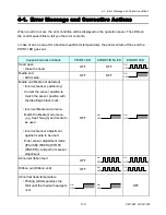
Page 128: ...e the head OFF OFF OFF ON Media end Add media OFF OFF OFF ON Media out Media not detected Incorrect sensor positioning Correct the sensor position to match the sensor position with the label tag s bla...

Page 129: ...stop Wait until the motor gets cool OFF ON OFF ON OFF Abnormal head resistance Due to defective thermal element Printing quality will degrade OFF OFF ON OFF ON Communication error Reception buffer ov...

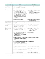
Page 130: ...40V 10 6 for 220V version 2 Is the fuse F1 on the Power Supply Unit blown 3 Is the Power Cable SA firmly connected between the Power Supply Unit and the Main PCB Unit CN10 4 Is the Ope pane Cable conn...

Page 131: ...ia feed mechanism work smoothly 4 Failure in the control circuit or in the paper feed motor driver 1 Re connect it firmly 2 Remove dust or foreign matter 3 Check clean and lubricate mechanical parts N...

Page 132: ...2 Failure in the control circuit 1 Close the head block correctly 2 Wait until the thermal head gets cool Printing resumes automatically 3 Wait until the PF motor gets cool Printing resumes automatica...

Page 133: ...702 on the Ribbon Main PCB SA and the Ribbon Motor F SA firmly 5 Is the cable connected between CN703 on the Ribbon Main PCB SA and the Ribbon Motor R SA firmly 6 Does the ribbon cooling fan work corr...

Page 134: ...Head Up Sensor PCB SA 3 Replace the Main PCB Unit Ribbon tension is not correctly controlled Tension sensor F R problem 1 Is the cable firmly connected between the Sensor Tension SA on the take up sid...

Page 135: ...Is the Media Sensor menu setting correct 2 Does the Transparent Sensor marker match with the bottom sensor Reflective Sensor marker 3 Is the sensor adjustment is performed against media to be used 4 I...

Page 136: ...djustment mode 4 Connect it firmly 5 Clean the LEDs to remove dust 6 Replace the Reflective Sensor PCB SA 7 Replace the Main PCB Unit 4 2 6 Operation Panel Problems Symptoms Checks Remedies Nothing is...

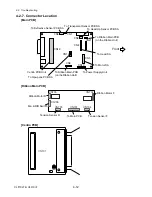
Page 137: ...SA To Reflective Sensor PCB SA To Head Up Sensor PCB SA To Motor SA To Head SA To Ope pane PCB SA To Power Supply Unit To Ribbon Main PCB on the Ribbon Unit To Ribbon Main PCB on the Ribbon Unit Front...

Page 138: ...CLP 621 CLP 631 CHAPTER 5 PARTS LISTS...

Page 139: ...eral Assembly Drawing No 1 5 5 Base Unit Drawing No 2 5 8 Mechanism Unit Drawing No 3 5 13 Head TT Unit Drawing No 4 5 17 PF Unit Drawing No 5 5 21 Sensor U Unit Drawing No 6 5 25 Control Panel Unit D...

Page 140: ...Chapter 5 Parts Lists CLP 621 CLP 631 5 3 CLP 621 CLP 631 Recommended Spare Parts List Revision Up List Sheet No Rev No Date 1 1 0 Dec 20 2006...

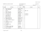
Page 141: ...1Z CSA 1 7 2 8 JM66808 0 Unit Main PCB With ROM ZM 1 For CLP 621Z CSE 1 8 2 8 JM66822 0 Unit Main PCB With ROM 631ZM 1 For CLP 631 CSE 1 9 2 33 JM66811 1 Unit Power Supply 100V PB F 1 For CSA 10 2 33...

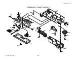
Page 142: ...Chapter 5 Parts Lists CLP 621 CLP 631 5 5 CLP 621 CLP 631 Drawing No 1 Parts List Location for General Assembly Revision Up List Sheet No Rev No Date 1 1 0 Dec 20 2006...

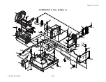
Page 143: ...Chapter 5 Parts Lists CLP 621 CLP 631 5 6 DRAWING NO 1 General Assembly Rev 0 1 7 8 2 3 4 2 10 11 12 9 5 2 13 14 10...

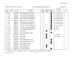
Page 144: ...Top Cover JM56738 0 1 For CLP 631 2 Screw PHT BH2T M3 0x14 E11230 140F 7 3 Cover Connector JM56205 0 1 4 Cap Case U JM56102 0 1 5 Cover Connector Case U JM56226 0 1 6 7 Cover Motor JM56225 0 1 8 Cove...

Page 145: ...Chapter 5 Parts Lists CLP 621 CLP 631 5 8 CLP 621 CLP 631 Drawing No 2 Parts List Location for Base Unit Revision Up List Sheet No Rev No Date 1 3 0 Dec 20 2006 2 3 0 Dec 20 2006 3 3 0 Dec 20 2006...

Page 146: ...Chapter 5 Parts Lists CLP 621 CLP 631 5 9 DRAWING NO 2 Base Unit Rev 0 3 4 19 20 23 21 22 6 31 7 5 17 18 24 24 16 8 11 10 9 15 12 13 14 10 28 29 28 29 30 14 32 33 27 26 25 1 2...

Page 147: ...B With ROM IT JM66802 0 1 For CLP 621 CSA 8 Unit Main PCB With ROM IT JM66821 0 1 For CLP 631 CSA 8 Unit Main PCB With ROM MT JM66801 0 1 For CLP 621 CSE 8 Unit Main PCB With ROM MT JM66819 0 1 For CL...

Page 148: ...6 C6390 050 2 For CSE 16 Plate Earth JM54101 0 1 17 Sheet Earth L JM44115 0 1 18 Sheet Earth R JM44114 0 1 19 Cable Ope Pane JM67900 1 1 20 SA Core JM59701 0 1 21 Cushion Ope Pane Cover JM59904 0 1 22...

Page 149: ...T for CLP 621 CLP 631 TITLE Base Unit Sheet No 3 3 Drawing No 2 Rev No 0 Location Part Name Part No Q ty Unit Remarks 2 32 SA Power Cable JM67745 1 1 33 Unit Power Supply 100V PB F JM66811 1 1 For CSA...

Page 150: ...Chapter 5 Parts Lists CLP 621 CLP 631 5 13 CLP 621 CLP 631 Drawing No 3 Parts List Location for Mechanism Unit Revision Up List Sheet No Rev No Date 1 2 0 Dec 20 2006 2 2 0 Dec 20 2006...

Page 151: ...Chapter 5 Parts Lists CLP 621 CLP 631 5 14 DRAWING NO 3 Mechanism Unit Rev 0 7 5 4 6 17 18 19 16 12 21 22 20 11 14 2 1 3 9 9 13 8 15 10 23 24 3...

Page 152: ...H M3 0x6 E00130 060F 1 6 Unit Head TT 621 JM19802 0 1 For CLP 621 6 Unit Head TT 631 JM19803 0 1 For CLP 631 7 Spring Head Up JM13601 0 1 8 Spring2 Head Up JM13605 0 1 9 Screw BH N M3 0x6 E00530 060WF...

Page 153: ...et No 2 2 Drawing No 3 Rev No 0 Location Part Name Part No Q ty Unit Remarks 3 20 Unit Sensor U JM29701 1 1 21 Label 2 Caution Head AH90935 0 1 22 Label 7 Caution Head AR99902 0 1 For CSA 22 Label 6 C...

Page 154: ...Chapter 5 Parts Lists CLP 621 CLP 631 5 17 CLP 621 CLP 631 Drawing No 4 Parts List Location for Head TT Unit Revision Up List Sheet No Rev No Date 1 2 0 Dec 20 2006 2 2 0 Dec 20 2006...

Page 155: ...Chapter 5 Parts Lists CLP 621 CLP 631 5 18 DRAWING NO 4 Head TT Unit Rev 0 1 17 17 16 2 18 3 4 5 6 7 8 9 10 11 13 14 15 1 19 20 3 21 3 3 12...

Page 156: ...0 1 For CLP 621 5 SA Head JM14706 0 1 For CLP 631 6 Spring Head L JM13603 0 1 7 SA Head Holder Base JM14704 1 1 8 Screw PH M3 0x5 E11130 050F 1 9 Holder Guide Sensor U JM14211 0 1 10 Lever Head Balanc...

Page 157: ...1 5 20 PARTS LIST for CLP 621 CLP 631 TITLE Head TT Unit Sheet No 2 2 Drawing No 4 Rev No 0 Location Part Name Part No Q ty Unit Remarks 4 20 Screw BH N M3 0x6 E00530 060WF 1 21 Shim Head Adjust JM141...

Page 158: ...Chapter 5 Parts Lists CLP 621 CLP 631 5 21 CLP 621 CLP 631 Drawing No 5 Parts List Location for PF Unit Revision Up List Sheet No Rev No Date 1 2 0 Dec 20 2006 2 2 0 Dec 20 2006...

Page 159: ...Chapter 5 Parts Lists CLP 621 CLP 631 5 22 DRAWING NO 5 PF Unit Rev 0 4 26 22 2 24 1 9 10 11 5 6 12 26 26 25 25 25 29 7 10 13 14 15 16 17 18 19 20 21 3 23 12 8 27 27 28...

Page 160: ...JM20202 0 1 6 Gear PF Idle JM20203 0 1 7 Gear PF1 JM20201 0 1 8 SA Plate Peeler JM44709 0 1 9 Frame Main JM44101 0 1 10 Wire Tie C6701 202 2 8432 L 100 11 SA Sensor Holder L JM24701 0 1 12 Damper Sens...

Page 161: ...ame Part No Q ty Unit Remarks 5 21 SA Main Plate R JM44702 0 1 22 Screw No 0 PH 1 M2 6x6 E01626 060F 1 23 Holder Guide Sensor L JM44207 0 1 24 Label 5 Caution Head AK99925 0 1 25 Washer EXT T 3 NI E50...

Page 162: ...Chapter 5 Parts Lists CLP 621 CLP 631 5 25 CLP 621 CLP 631 Drawing No 6 Parts List Location for Sensor U Unit Revision Up List Sheet No Rev No Date 1 1 0 Dec 20 2006...

Page 163: ...Chapter 5 Parts Lists CLP 621 CLP 631 5 26 DRAWING NO 6 Sensor U Unit Rev 0 4 16 3 2 1 9 10 11 5 8 6 12 7 13 14 15...

Page 164: ...2 4 Cap Sensor Frame L JM24210 0 1 5 Washer Plain 2x5x03 E50120 003F 1 6 Screw PHT PT2T M2 0x8 E11220 080F 1 7 Holder Sensor U JM24205 1 1 8 Damper Sensor L JM29902 0 1 9 SA Transparent Sensor PCB JM...

Page 165: ...Chapter 5 Parts Lists CLP 621 CLP 631 5 28 CLP 621 CLP 631 Drawing No 7 Parts List Location for Control Panel Unit Revision Up List Sheet No Rev No Date 1 1 0 Dec 20 2006...

Page 166: ...Chapter 5 Parts Lists CLP 621 CLP 631 5 29 DRAWING NO 7 Control Panel Unit Rev 0 4 3 2 1 5...

Page 167: ...1 CLP 631 TITLE Control Panel Unit Sheet No 1 1 Drawing No 7 Rev No 0 Location Part Name Part No Q ty Unit Remarks 7 1 Cover Ope Pane JM56204 0 1 2 Switch Key JM56207 0 1 3 LED Window JM56208 0 1 4 SA...

Page 168: ...Chapter 5 Parts Lists CLP 621 CLP 631 5 31 CLP 621 CLP 631 Drawing No 8 Parts List Location for Ribbon Unit Revision Up List Sheet No Rev No Date 1 3 0 Dec 20 2006 2 3 0 Dec 20 2006 3 3 0 Dec 20 2006...

Page 169: ...AWING NO 8 Ribbon Unit Rev 0 10 11 13 16 17 21 23 22 18 19 15 20 14 18 12 21 23 24 25 26 4 5 6 2 1 7 9 46 42 39 35 34 33 32 40 45 22 44 43 40 23 21 38 37 36 35 34 3 1 39 17 30 19 18 18 12 32 16 33 10...

Page 170: ...M3 0x6 NI E00530 060WF 4 7 Screw PH M2 6x3 E00126 030F 4 8 SA Ribbon Motor R JM35703 0 1 9 SA Ribbon Motor F JM35702 0 1 10 Screw PH PW M2 0x8 E00620 080F 2 11 SA Tension Adjust Lever F JM34711 0 1 1...

Page 171: ...F JM34715 0 1 26 Sheet Static Eliminator 621 JM29909 0 1 27 SA Tension Adjust Lever R JM34712 0 1 28 SA Ribbon Sub Adjust Lever R JM34714 0 1 29 Spring R Ribbon Tension JM33605 0 2 30 SA Ribbon Senso...

Page 172: ...ng No 8 Rev No 0 Location Part Name Part No Q ty Unit Remarks 8 41 Gear 2 Ribbon JM30202 0 2 42 Gear 5F Ribbon JM30206 0 1 43 Screw PHT 2 M3 0x8 NI E10130 080WF 2 44 Catch Ribbon Holder JM34203 0 2 45...

Page 173: ...Chapter 5 Parts Lists CLP 621 CLP 631 5 36 CLP 621 CLP 631 Drawing No 9 Parts List Location for Ribbon Unit Fan SA2 Revision Up List Sheet No Rev No Date 1 1 0 Dec 20 2006...

Page 174: ...Chapter 5 Parts Lists CLP 621 CLP 631 5 37 DRAWING NO 9 Ribbon Unit Fan SA2 Rev 0 1 2 4 3 5 6 3...

Page 175: ...an SA2 Sheet No 1 1 Drawing No 9 Rev No 0 Location Part Name Part No Q ty Unit Remarks 9 1 Cover L Ribbon Unit JM34202 0 1 2 Knob Ribbon Direction JM34212 0 1 3 Screw BHT 2 M3X6 NI E10530 060WF 6 4 SA...

Page 176: ...Chapter 5 Parts Lists CLP 621 CLP 631 5 39 CLP 621 CLP 631 Drawing No 10 Parts List Location for Accessories Revision Up List Sheet No Rev No Date 1 1 0 Dec 20 2006...

Page 177: ...Chapter 5 Parts Lists CLP 621 CLP 631 5 40 DRAWING NO 10 Accessories Rev 0 3 2 4 1...

Page 178: ...C6009 000 1 For CSA 1 Cord Set OE Straight C6009 200 1 For CSE 1 Cord Set UK C6009 300 For CSE 2 Shaft Paper JM79202 0 1 3 Flange Paper Wide JM79201 0 1 4 Ribbon Core 25x114 JM39902 0 1 Cleaner Head J...

Page 179: ...CHAPTER 6 CIRCUIT DIAGRAMS CLP 621 CLP 631...

Page 180: ...r 6 14 Circuit Diagram Main PCB 12 14 Centronics I F 6 15 Circuit Diagram Main PCB 13 14 Serial I F 6 16 Circuit Diagram Main PCB 14 14 USB I F 6 17 Circuit Diagram Power Supply PCB 120V 6 18 Circuit...

Page 181: ...Chapter 6 Circuit Diagrams Inter Connection 1 2 3 4 5 6 7 8 A B C D 8 7 6 5 4 3 2 1 D A Title Number Revision Size A4 Date Sheet of File Drawn By A INNER CONNECTION 1 1 C B 6 3 CLP 621 CLP 631...

Page 182: ...Circuit Diagram Main PCB 1 14 CPU 1 2 1 2 3 4 5 6 7 8 A B C D 8 7 6 5 4 3 2 1 D C B A Title Number Revision Size A4 Date Sheet of File Drawn By 1 14 A MAIN PCB CPU CIRCUIT 1 1 14 JM66801 JM66802 22 No...

Page 183: ...Circuit Diagram Main PCB 2 14 CPU 2 2 1 2 3 4 5 6 7 8 A B C D Title Number Revision Size A4 Date Sheet of File Drawn By 2 14 A JM66801 JM66802 22 Nov 2004 MAIN PCB CPU CIRCUIT 2 2 14 8 7 6 5 4 3 2 1 D...

Page 184: ...ms Circuit Diagram Main PCB 3 14 ROM 1 2 3 4 5 6 7 8 A B C D 8 7 6 5 4 3 2 1 D C B A Title Number Revision Size A4 Date Sheet of File Drawn By 3 14 A JM66801 JM66802 22 Nov 2004 MAIN PCB ROM CIRCUIT 3...

Page 185: ...ms Circuit Diagram Main PCB 4 14 RAM 1 2 3 4 5 6 7 8 A B C D 8 7 6 5 4 3 2 1 D C B A Title Number Revision Size A4 Date Sheet of File Drawn By 4 14 A JM66801 JM66802 22 Nov 2004 MAIN PCB RAM CIRCUIT 4...

Page 186: ...uit Diagram Main PCB 5 14 Custom IC 1 2 3 4 5 6 7 8 A B C D 8 7 6 5 4 3 2 1 D C B A Title Number Revision Size A4 Date Sheet of File Drawn By 5 14 A JM66801 JM66802 22 Nov 2004 MAIN PCB GATE ARRARY CI...

Page 187: ...t Diagram Main PCB 6 14 Head Control 1 2 3 4 5 6 7 8 A B C D 8 7 6 5 4 3 2 1 D C B A Title Number Revision Size A4 Date Sheet of File Drawn By 6 14 A JM66801 JM66802 22 Nov 2004 MAIN PCB HEAD CONTROL...

Page 188: ...agram Main PCB 7 14 PF Motor Control 1 2 3 4 5 6 7 8 A B C D 8 7 6 5 4 3 2 1 D C B A Title Number Revision Size A4 Date Sheet of File Drawn By 7 14 A JM66801 JM66802 22 Nov 2004 MAIN PCB PF MOTOR CONT...

Page 189: ...Circuit Diagram Main PCB 8 14 Sensor 1 2 3 4 5 6 7 8 A B C D 8 7 6 5 4 3 2 1 D C B A Title Number Revision Size A4 Date Sheet of File Drawn By 8 14 A JM66801 JM66802 22 Nov 2004 MAIN PCB SENSOR CIRCUI...

Page 190: ...t Diagram Main PCB 9 14 Power Buzzer 1 2 3 4 5 6 7 8 A B C D 8 7 6 5 4 3 2 1 D C B A Title Number Revision Size A4 Date Sheet of File Drawn By 9 14 A JM66801 JM66802 22 Nov 2004 MAIN PCB POWER BUZZER...

Page 191: ...it Diagram Main PCB 10 14 Connector 1 2 3 4 5 6 7 8 A B C D 8 7 6 5 4 3 2 1 D C B A Title Number Revision Size A4 Date Sheet of File Drawn By 10 14 A JM66801 JM66802 22 Nov 2004 MAIN PCB CONNECTOR CIR...

Page 192: ...iagram Main PCB 11 14 Cutter Peeler 1 2 3 4 5 6 7 8 A B C D 8 7 6 5 4 3 2 1 D C B A Title Number Revision Size A4 Date Sheet of File Drawn By 11 14 A JM66801 JM66802 22 Nov 2004 MAIN PCB CUTTER PEELER...

Page 193: ...iagram Main PCB 12 14 Centronics I F 1 2 3 4 5 6 7 8 A B C D 8 7 6 5 4 3 2 1 D C B A Title Number Revision Size A4 Date Sheet of File Drawn By 12 14 A JM66801 JM66802 22 Nov 2004 MAIN PCB CENTRONICS I...

Page 194: ...it Diagram Main PCB 13 14 Serial I F 1 2 3 4 5 6 7 8 A B C D 8 7 6 5 4 3 2 1 D C B A Title Number Revision Size A4 Date Sheet of File Drawn By 13 14 A JM66801 JM66802 22 Nov 2004 MAIN PCB SERIAL IF CI...

Page 195: ...ircuit Diagram Main PCB 14 14 USB I F 1 2 3 4 5 6 7 8 A B C D 8 7 6 5 4 3 2 1 D C B A Title Number Revision Size A4 Date Sheet of File Drawn By 14 14 A JM66801 JM66802 22 Nov 2004 MAIN PCB USB CIRCUIT...

Page 196: ...rams Circuit Diagram Power Supply PCB 120V 1 2 3 4 5 6 7 8 A B C D 8 7 6 5 4 3 2 1 D C B A Title Number Revision Size A4 Date Sheet of File Drawn By A POWER SUPPLY CIRCUIT 100V 1 1 22 Nov 2004 CZ52082...

Page 197: ...rams Circuit Diagram Power Supply PCB 220V 1 2 3 4 5 6 7 8 A B C D 8 7 6 5 4 3 2 1 D C B A Title Number Revision Size A4 Date Sheet of File Drawn By A POWER SUPPLY CIRCUIT 200V 1 1 22 Nov 2004 CZ53082...

Page 198: ...iagram Ribbon Main PCB 1 4 Motor Control 1 2 3 4 5 6 7 8 A B C D 8 7 6 5 4 3 2 1 D C B A Title Number Revision Size A4 Date Sheet of File Drawn By 1 4 A RIBBON MAIN PCB MOTOR CONTROL CIRCUIT 1 4 JM667...

Page 199: ...am Ribbon Main PCB 2 4 Motor VCC Control RIBBON MAIN PCB MOTOR VCC CONTROL CIRCUIT 2 4 JM66740 1 2 3 4 5 6 7 8 A B C D 8 7 6 5 4 3 2 1 D C B A Title Number Revision Size A4 Date Sheet of File Drawn By...

Page 200: ...rcuit Diagram Ribbon Main PCB 3 4 Sensor 1 2 3 4 5 6 7 8 A B C D 8 7 6 5 4 3 2 1 D C B A Title Number Revision Size A4 Date Sheet of File Drawn By 3 4 A 22 Nov 2004 RIBBON MAIN PCB SENSOR CIRCUIT 3 4...

Page 201: ...bbon Main PCB 4 4 12V Fan DIR SW Control 1 2 3 4 5 6 7 8 A B C D 8 7 6 5 4 3 2 1 D C B A Title Number Revision Size A4 Date Sheet of File Drawn By 4 4 A 22 Nov 2004 RIBBON MAIN PCB 12V FAN DIR SW CONT...

Page 202: ...60 C302 1000p R303 360 C303 1000p R302 360 R306 22k R305 22k R307 22k R308 22k V3R3 V3R3 V3R3 1 2 3 4 5 6 7 8 9 10 11 12 1 2 5 3 4 1 2 5 3 4 1 2 5 3 4 1 2 5 3 4 PRTLEDIN ERRLEDIN MODE STOP PAUSE FEED...

Page 203: ...27 28 29 30 31 32 33 34 35 36 37 38 39 40 1 2 DATA6 xFAULT xPRIME DATA4 IEEE1284 xATFD XT PE DATA7 DATA5 DATA3 xSTROBE DATA2 SLCT DATA1 BUSY xACKNLG xSLCT IN xFAULT S GND BUSY S GND S GND F GND S GND...

Page 204: ...Diagrams Circuit Diag am Tension Sensor PCB 1 2 3 4 5 6 7 8 A B C D 8 7 6 5 4 3 2 1 D C B A Title Number Revision Size A4 Date Sheet of File Drawn By 1 1 A 22 Nov 2004 SA TENSION SENSOR PCB JM66745 CL...

Page 205: ...B 1 2 3 4 5 6 7 8 A B C D 8 7 6 5 4 3 2 1 D C B A Title Number Revision Size A4 Date Sheet of File Drawn By A REFRECTIVE SENSOR CIRCUIT 1 1 JM66730 7 Nov 2003 CN501 CHP1505 0101 D502 GL100MN0MP D501 G...

Page 206: ...nsparent Sensor PCB 1 2 3 4 5 6 7 8 A B C D 8 7 6 5 4 3 2 1 D C B A Title Number Revision Size A4 Date Sheet of File Drawn By A TRANSPARENT SENSOR CIRCUIT 1 1 JM66725 7 Nov 2003 TR401 PT4800F6 CN401 0...

Page 207: ...Sensor PCB 1 2 3 4 5 6 7 8 A B C D Title Number Revision Size A4 Date Sheet of File Drawn By A HEAD UP SENSOR CIRCUIT 1 1 JM66715 7 Nov 2003 PI201 SG 278 C201 1000p C202 1000p CN201 S3B PH K S 1 2 3 4...

Page 208: ...APPENDICES CLP 621 CLP 631...

Page 209: ...1 Main PCB AP 4 B 2 Power Supply PCB 120V 220V AP 6 B 3 Ribbon Main PCB AP 7 B 4 Ope pane PCB AP 8 B 5 Centro PCB AP 8 B 6 Transparent Sensor PCB B 7 Reflective Sensor PCB AP 9 B 8 Head Up Sensor PCB...

Page 210: ...A External Size Diagram A External Size Diagram AP 3 CLP 621 CLP 631 Unit mm inch Approx 289 11 4 Approx 263 10 3 Approx 231 9 1...

Page 211: ...B Mounting Diagrams B Mounting Diagrams B Mounting Diagrams CLP 621 CLP 631 AP 4 AP 4 B 1 Main PCB Main PCB Parts side...

Page 212: ...B Mounting Diagrams AP 5 CLP 621 CLP 631 Main PCB Solder side...

Page 213: ...B Mounting Diagrams CLP 621 CLP 631 AP 6 AP 6 B 2 Power Supply PCB 120V 220V B 2 Power Supply PCB 120V 220V...

Page 214: ...B Mounting Diagrams AP 7 CLP 621 CLP 631 B 3 Ribbon Main PCB Parts side Solder side...

Page 215: ...CLP 621 CLP 631 AP 8 B 4 Ope pane PCB Parts side Solder side POWERON K K K K PRINT CONDITION ERROR JM667 MADE IN JAPAN MOSCAUTION JM66930 01 PAUSE FEED STOP MODE CN301 12 11 1 2 D301 D302 D303 D304 B...

Page 216: ...31 B 6 Transparent Sensor PCB B 7 Reflective Sensor PCB C TR401 CN401 E 01 D502 D501 TR501 A A C K K E CN501 B 8 Head Up Sensor PCB 1 2 3 4 1 3 CN201 PI201 C202 C201 B 9 Tension Sensor PCB Parts side...

Page 217: ......
Reviews: