2-3. Operation Panel
CLP-621 & CLP-631
2-40
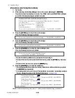
Service mode:
You can perform checks such as “head check” and “counter print” to print the total print
length since the printer is firstly used.
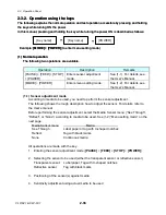
(3-2) How to enter the Factory/Service Mode
How to enter Factory/Service mode differs from the “user menu setup mode” operation.
However, once you have entered Factory/Service mode, the basic operation is the same
as that for the “user menu setup mode” explained in the User’s manual.
The Factory/Service mode menu appears at the top of the user menus as follows:
PAUSE
STOP
FEED
MODE/REPEAT
No / Next item / Increase item
Yes / Select / Save
Next digit
Exit the current menu or the
VuePrint menu system
The menu operation principle is the same as for the “user menu setup mode” operation.
The keys to be used and the functions are as follow:
All keys + POWER
Factory Mode menu
Service Mode menu
Page Setup menu
System Setup menu
After Print menu
Interface menu
Do you want to change the menu
settings? Yes=(PAUSE) No=(STOP)
Top menus
Added
[PAUSE (Yes)]
VuePrint
menu
system
Do you want to print the current menu
settin
[PAUSE (Yes)]
To print
gs? Yes=(PAUSE) No=(STOP)
: Different operation from the “user menu setup mode”
Summary of Contents for CLP-621
Page 1: ...Technical Manual CLP 621 CLP 631 Thermal Transfer Barcode Label Printer JM74961 00F 1 00E 0701...
Page 2: ...CLP 621 CLP 631 ii Copyright 2007 by CITIZEN SYSTEMS JAPAN CO LTD...
Page 4: ...CHAPTER 1 SPECIFICATIONS CLP 621 CLP 631...
Page 13: ...CHAPTER 2 OPERATING PRINCIPLES CLP 621 CLP 631...
Page 73: ...CHAPTER 3 DISASSEMBLY AND MAINTENANCE CLP 621 CLP 631...
Page 126: ...CLP 621 CLP 631 CHAPTER 4 TROUBLESHOOTING...
Page 138: ...CLP 621 CLP 631 CHAPTER 5 PARTS LISTS...
Page 166: ...Chapter 5 Parts Lists CLP 621 CLP 631 5 29 DRAWING NO 7 Control Panel Unit Rev 0 4 3 2 1 5...
Page 177: ...Chapter 5 Parts Lists CLP 621 CLP 631 5 40 DRAWING NO 10 Accessories Rev 0 3 2 4 1...
Page 179: ...CHAPTER 6 CIRCUIT DIAGRAMS CLP 621 CLP 631...
Page 208: ...APPENDICES CLP 621 CLP 631...
Page 212: ...B Mounting Diagrams AP 5 CLP 621 CLP 631 Main PCB Solder side...
Page 214: ...B Mounting Diagrams AP 7 CLP 621 CLP 631 B 3 Ribbon Main PCB Parts side Solder side...
Page 217: ......


