background image

3.9 Connecting the Cash Drawer

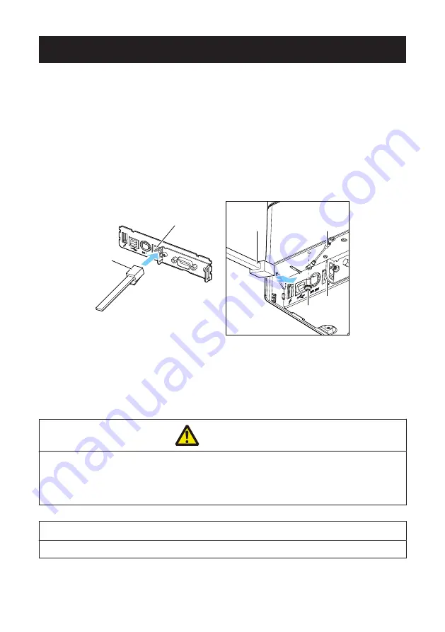
1. Turn off the power.

2. Confirm the orientation of the cash drawer kick-out cable connector and connect it to

the cash drawer kick-out connector at the back of the printer.

3. Remove the screw for the ground wire.

4. Screw the cash drawer’s ground wire to the body of the printer.

2

1

3

1

4

2

1. Cash drawer kick-out connector
2. Cash drawer kick-out cable connector
3. Ground wire
4. Screw for ground wire

 CAUTION

n

Connect only the cash drawer kick-out cable to this connector. (Do not connect a telephone

line.)

n

Hold the connector of the drawer kick cable perpendicular and straight when connecting or

disconnecting it. Doing it at an angle may cause the connector to misconnect.

Notes

Signals cannot be output from the cash drawer kick-out connector while printing.

(1) Connector pin configuration

– 61 –

Summary of Contents for CT-E601

Page 1: ...LINE THERMAL PRINTER MODEL CT E601 User s Manual ...

Page 2: ...vista por la sobre residuos de aparatos eléctricos y electrónicos RAEE vigente únicamente en la Unión Europea Ge Fr Sp It Se desiderate gettare via questo prodotto non mescolatelo ai rifiuti generici di casa Esiste un sistema di raccolta separato per i prodotti elettronici usati in conformità alla legislazione RAEE valida solo all interno dell Unione Europea Ge Fr Sp It Du Deponeer dit product nie...

Page 3: ...nstruction manual maycause interference to radio communications It has been tested and found to complywith the limits for a Class A computing device pursuant to Subpart J of Part 15 of FCCRules which are designed to provide reasonable protection against such interferencewhen operated in a commercial environment Operation of this equipment in aresidential area is likely to cause interference in whi...

Page 4: ...rom the loss of data caused by accidents re pairs tests or other occurrences l If you find omissions errors or have questions please contact your Citizen Systems dealer l If you find any pages missing or out of order contact your Citizen Systems dealer for a replacement NOTICE IN NO EVENT SHALL CITIZEN INCLUDING ANY OF ITS PARENT SUBSIDIARY OR AFFILIATED COMPANIES BE LIABLE TO PURCHASER OR OTHERS ...

Page 5: ...tning are trademarks of Apple Inc registered in the U S and other countries tvOS is a trade mark of Apple Inc The trademark iPhone is used in Japan with a license from Ai phone K K l EPSON and ESC POS are registered trademarks of Seiko Epson Corporation l QR Code is a registered trademark of DENSO WAVE INCORPORATED l Ethernet is a registered trademark of Fuji Xerox Corporation l Bluetooth is a reg...

Page 6: ...ree of hazard and damage that could occur if the printer is improperly operated by ignoring the instructions indicated by the warning symbols Be sure to read this information carefully WARNING Neglecting precautions indicated by this symbol may result in fatal or serious injury CAUTION Neglecting precautions indicated by this symbol may result in injury or damage to property This symbol is used to...

Page 7: ... object such as paper clips pins or screws into the printer n Do not place a flower vase pot or anything containing water on the printer n Do not spill coffee soft drinks or any other liquid into the printer n Do not spray insecticide or any other chemical liquid over the printer n Dropping a metallic foreign object into the printer may cause printer fail ure fire or electric shock Should it occur...

Page 8: ...cause an unexpected injury or accident if they are handled or used improperly l Keep the power cord and signal cables out of the reach of children Also chil dren should not be allowed to gain access to any internal part of the printer l The plastic bag the printer came in must be disposed of properly or kept away from children Wearing it over the head may lead to suffocation 8 ...

Page 9: ... near a radio or TV set or from supplying it from the same electric outlet as these appliances l Avoid using the printer interconnected with a cable or cord that has no protec tion against noise For interconnections use shielded or a twisted pair of cables and ferrite cores or other anti noise devices l Avoid using the printer with a device that is a strong source of noise u The printer may have a...

Page 10: ...plosion could result Telephone line ground Lightning rod l If lightning strikes a large surge of current may cause fire or shock Water pipes l Plastic water pipes should not be used for grounding Those approved by a Waterworks Department may be used n Before connecting or disconnecting the grounding lead to or from the printer always unplug it from the electric outlet 10 ...

Page 11: ...ilure emission of smoke fire or electric shock u An overload may cause the power cord to overheat catch fire or the circuit breaker to trip l Do not allow anything to rest on the power cord Do not place the printer where the power cord may be stepped on l Do not subject the power cord to severe bending twisting or pulling Do not carry the product while it is in this state either l Do not attempt t...

Page 12: ...WARNING l Hold the plug and connector when plugging or unplugging the power cord or signal cable after turning off the printer and the appliance connected to it 12 ...

Page 13: ...nter with the paper roll inside l Printer failure or damage may occur To prevent possible malfunction or failure observe the following l Do not open the paper cover during printing l Avoid operating the printer without paper properly loaded l Avoid the use of paper not complying with specifications u May result in poor print quality l Avoid using torn pieces of paper or paper spliced with plastic ...

Page 14: ...stems serv ice for repair l Be careful that the covers do not pinch your hands or fingers l Be careful of the sharp edges on the printer Do not allow them to injure you or damage property u May result in electric shock burn or injury If the printer emits smoke an odd smell or unusual noise while printing immediately abort the current print session and unplug the printer from the electric outlet DA...

Page 15: ...CAUTION The thermal head is at a dangerously high temperature immediately after printing Allow it to cool off before starting maintenance work 15 ...

Page 16: ...AN Interface Board 46 3 7 Lightning USB host interface board 53 3 8 USB Power Supply Port 59 3 9 Connecting the Cash Drawer 61 3 10 Precautions for Installing the Printer 63 3 11 Adjusting the Paper Near end Sensor 64 3 12 Loading Paper 65 3 13 58 mm Width Roll Paper Partition 68 3 14 Mounting the Cable Cover 69 3 15 Precautions for Creating Applications and Practical Operations 70 3 16 Download S...

Page 17: ... Paper Jams 78 4 8 Precautions for Performing Printing for Which Printing Speed Changes 78 5 OTHER 79 5 1 External Views and Dimensions 79 5 2 Printing Paper 80 5 3 Manual Setting of Memory Switches 82 17 ...

Page 18: ...d with a standard USB power supply port l Energy saving function ENERGY STAR compliant l Interchangeable interface board l XML Web print function included wired LAN or wireless LAN model l USB host function capable of controlling peripheral devices included wired LAN Bluetooth or Lightning USB host model l The Lightning model can transmit data even during fast charging of Apple devices l Printer s...

Page 19: ...eated characters and logos can be saved in the user memory l Support for barcodes including 2D barcodes l Apple MFi certified Bluetooth and USB Lightning communication support Blue tooth model Lightning model 19 ...

Page 20: ...1 2 Unpacking Make sure the following items are included with your printer NAME QUAN TITY ILLUSTRATION Printer 1 AC Adapter 37AD5 1 AC power cord 1 Quick Start Guide 2 20 ...

Page 21: ...USB NN USB 3 Market U North America E Europe 4 Body case color WH Pure white BK Black Contact us in advance for special combinations some of which may not be available 1 4 Basic Specifications Item Specifications Model CT E601 Print method Line thermal dot print method Print widths 72 mm 576 dots 68 25 mm 546 dots 64 mm 512 dots 52 5 mm 420 dots 48 75 mm 390 dots 48 mm 384 dots 45 mm 360 dots fact...

Page 22: ...unction USB3 port Ethernet 100BASE TX 10BASE T Wireless LAN IEEE802 11n IEEE802 11a IEEE802 11g IEEE802 11b Bluetooth Version Bluetooth 3 0 EDR Profile SPP Serial Port Protocol iAP iPod Accessory Protocol Power class Class2 Bluetooth USB host function Version Bluetooth 4 2 EDR Profile SPP Serial Port Protocol iAP2 iPod Accessory Protocol Power class Class2 USB power supply port Max 2 1 A Cash draw...

Page 23: ...le refer to typical models The number of columns varies depend ing on specifications 2 Characters appear small because the dimensions include a blank area surrounding each character 3 This standard applies when our AC Adapter 37AD5 is used 23 ...

Page 24: ...e paper cover 3 POWER button Hold down two or three seconds to switch power on or off 4 FEED button Press this button to feed paper In case of a cutter error press the FEED button with the paper cover closed after removing the cause The printer enters the mode for setting memory switches and running self test Refer to 4 4 Self Test Refer to 5 3 Manual Setting of Memory Switches 5 Operation panel 6...

Page 25: ... tected May also light or flash when other abnormalities are detected CUTTER LED Green Flashes when a cutter error is detected May also light or flash when other abnormalities are detected COVER LED Green Lights or flashes when an open paper cover is detec ted May also light or flash when other abnormalities are detected SERVICE LED Orange Flashes when an unrecoverable printer abnormality is detec...

Page 26: ...rface connector serial USB etc Connect to the interface cable 2 Cash drawer kick out connector Connect to the cable from the cash drawer 3 Power connector Connect to the AC adapter cable 4 USB connector 5 USB power supply port Supply power to a USB device 26 ...

Page 27: ...ton to change paper near end sensor Change the position of the paper near end sensor to match the paper being used Refer to 3 11 Adjusting the Paper Near end Sensor 4 Paper end PE sensor Detects when there is no paper Printing stops when this sensor detects there is no paper 5 Platen Feeds the paper Do not remove the platen except to do maintenance 6 Auto cutter Cuts the paper Refer to 5 3 Manual ...

Page 28: ...of the paper 9 Paper anti curling damper Damper for reducing the warp of the paper 10 Paper jamming sensor Sensor for detecting paper jam and stopping the printing Notes The anti curling roller and anti curling damper do not straighten the paper completely 28 ...

Page 29: ...he printer becomes the state of USB linked power OFF after 3 seconds when PC power off or USB connection lost This mode is canceled when the PC is turned back on or when a USB connection is established Notes n Since the POWER LED is unlit when the state of USB linked power OFF it cannot be identi fied from the power OFF n Pressing the POWER button while the state of USB linked power OFF turns on p...

Page 30: ...specific head heating element If no data is received within 15 seconds after each cut or print the print position is automatically slid N dots to the right The original print position is returned to at the next slide timing N is the MSW8 6 setting value Notes n If the right margin is too narrow this may result in some print characters being cut off n This function is disabled under initial setting...

Page 31: ...e an AC power source that does not also supply power to equipment that generates elec tromagnetic noise n Pulling on the AC power cord may damage it cause a fire electric shock or break a wire n If a lightning storm is approaching unplug the AC power cord from the electric outlet A light ning strike may cause a fire or electric shock n Keep the AC power cord away from heat generating appliances Th...

Page 32: ...rface cable and connect it to the port 3 Insert the other connector firmly into the interface port of the host computer CAUTION n When disconnecting the cable always hold the connector n Place the interface cable so that people do not trip on it Notes Do not connect multiple interfaces at the same time Use a serial cable with the connection layout shown below 32 ...

Page 33: ...9 pin female 9 pin female cable Printer PC Signal Pin Pin Signal RXD 2 2 RXD TXD 3 3 TXD DTR 4 4 DTR SG 5 5 SG DSR 6 6 DSR RTS 7 7 RTS CTS 8 8 CTS 33 ...

Page 34: ...the connector n Place the interface cable so that people do not trip on it n Be careful not to insert the USB cable into the cash drawer kick out connector Notes n Do not connect multiple interfaces at the same time n To connect more than one printer to a single computer by USB you must change the serial number of the USB interface n There are models with a USB port on the interface board side Wit...

Page 35: ...ce board side If USB cables are connected to both priority will be given to communication of the one connec ted to the connector on the main unit side Bluetooth status LED Status Description LED Status Detection standby Discoverable Standing by for detection and connection Connection standby Connectable Standing by for connection iOS connection Data session unop ened Communicating iOS data session...

Page 36: ...ection between the host PC is terminated 2 Configuring pairing settings Normally selecting the printer during device detection will transition directly to pair ing settings Notes Some host PC configurations and models may not transition directly to pairing settings after the printer is selected during device detection The operation required to configure pairing settings depends on whether SSP secu...

Page 37: ... This function is enabled when shipped from the factory MSW13 6 Auto reconnection can take some time to connect when the host is not an iOS de vice n Even if the partner device is an iOS device the conditions below can interfere with the auto reconnection function When you want Bluetooth communication to cut off after printing is complete When there are multiple iOS devices printing on the same pr...

Page 38: ...ces can control peripheral devices connected via a USB port Connecting a Peripheral Device 1 Turn off the power 2 Connect the cable of a peripheral device to this port Notes A peripheral device cannot be controlled if it is connected to the USB power supply port Be sure to connect it to the USB port of the interface board 38 ...

Page 39: ...a peripheral device The connected peripheral device can be controlled 2 For host computer communication Connect with a host computer The printer and host computer will communicate via USB Refer to 3 3 USB Interface 3 For supplying power Connect a mobile device or other USB device Power can be supplied to a connected USB device This port does not support USB data communication Refer to 3 8 USB Powe...

Page 40: ...oth devices Confirm that Bluetooth is enabled on the host PC before searching for Bluetooth devices This product will show up as CT E601_XX XX is last 2 digits of unique BD ad dress when it is detected Select this product from among the detected devices Note You can search for devices and change the names When memory switch MSW13 5 is set to No Response nothing is displayed by device detection Wit...

Page 41: ... are upper case Example If the address is 01 23 45 67 89 AB the passkey is 89AB If you delete paring information from the host PC without deleting the corresponding pairing information on the printer the printer may not show up if you detect devices again with the host PC When deleting pairing information press and hold the panel button for at least three seconds and after the buzzer sounds press ...

Page 42: ...t is not an iOS de vice n Even if the partner device is an iOS device the conditions below can interfere with the auto reconnection function When you want Bluetooth communication to cut off after printing is complete When there are multiple iOS devices printing on the same printer Under such conditions disable auto reconnection 42 ...

Page 43: ...g self test press the FEED button 3 times Auto reconnect Valid During self test press the FEED button 4 times Auto reconnect Invalid At the end of self test new setting will be printed as Auto reconnect Valid or Invalid Refer to 4 4 Self Test 43 ...

Page 44: ... on printer power 2 Press the panel button within one second after starting the printer The setting changes in accordance with the number of times you press the panel button Two presses Discovery possible Three presses No response After these operations the printer restarts l Print the interface board state After starting the printer pressing the panel button once prints the interface board state ...

Page 45: ...sion 2 Address of equipped Bluetooth module 3 Bluetooth name 4 Response profile in Bluetooth transmission 5 Bluetooth setting state 6 Name of connected USB device No connection is displayed when there is no connection 7 Board status 45 ...

Page 46: ...ower 2 Confirm the orientation of the interface cable and connect it to the port 3 Connect the other connector to a hub router or similar device CAUTION n When disconnecting the cable always hold the connector n Place the interface cable so that people do not trip on it n Hold the connector of the LAN cable perpendicular and straight when connecting or discon necting it Doing it at an angle may ca...

Page 47: ... connected to the USB power supply port Be sure to connect it to the USB port of the interface board Connecting the wireless LAN adapter 1 Turn off the power 2 Connect the wireless LAN adapter to the connector Notes The wireless LAN cannot be used when connected to the USB power supply connector Be sure to connect it to the USB connector on the interface board 47 ...

Page 48: ... Even when a wireless LAN adapter is connected you can connect peripheral devi ces to available ports 2 For host computer communication Connect with a host computer The printer and host computer will communicate via USB Refer to 3 3 USB Interface 3 For supplying power Connect a mobile device or other USB device Power can be supplied to a connected USB device This port does not support USB data com...

Page 49: ...Entering setting mode Hold down the panel button A buzzer will sound once to indicate that setting mode has been entered You can use setting mode to read factory settings If no operation is performed for 3 seconds in configuration mode the mode switches back to normal mode l Returning to factory settings Enter the board setting mode and then hold down the panel button This returns the board to its...

Page 50: ...r con nection No network con nection Lit Unlit Board is connected with a printer Connected by wired LAN Lit Flashing 1 second cycle Getting an IP address from the DHCP server over wired LAN Wired LAN opera tion Lit Lit Network operation being performed over wired LAN Connected by wireless LAN Flashing 2 second cycle Flashing 1 second cycle Connecting to an access point or get ting an IP address fr...

Page 51: ... with a web browser and change board settings Starting up Web Manager 1 Start up a web browser 2 In the address field input the board s IP address and then press Enter HOME Screen This is the Web manager home screen The following screen is an example for a wireless LAN Here press the CONFIG button 51 ...

Page 52: ...ings l User Name Input a board administrator user name Initial setting admin l Password Input the administrator user password Initial setting admin l Login button After inputting an administrator user name and password click the Login button This displays the setting screen For details about settings refer to the separate manual 52 ...

Page 53: ... the Interface Cable 1 Turn off the power 2 Confirm the orientation of the interface cable and connect it to the port 3 Connect the other connector to the interface connector of an Apple device CAUTION n When disconnecting the cable always hold the connector n Place the interface cable so that people do not trip on it n Hold the connector of the LAN cable perpendicular and straight when connecting...

Page 54: ... Turn off the power 2 Connect the cable of a peripheral device to this port Notes A peripheral device cannot be controlled if it is connected to the USB power supply port Be sure to connect it to the USB port of the interface board 54 ...

Page 55: ...able Fast charging of the Apple device can also be carried out 3 For host computer communication Connect with a host computer The printer and host computer will communicate via USB Refer to 3 3 USB Interface 4 For supplying power Connect a mobile device or other USB device Power can be supplied to a connected USB device This port does not support USB data communication The Lightning model does not...

Page 56: ...of Apple devices 4 Green LED This LED indicates the communication status with the printer 5 Red LED This LED indicates the connection status with an Apple device Notes n Only connect peripheral devices specified by our company to the USB port n Only plug in remove peripheral devices when the printer power is turned off n Operation of this board will start about 30 seconds after the power is turned...

Page 57: ...terface board state After starting the printer pressing the panel button once prints the interface board state 1 System information of this interface board 2 Information of the printer connected to this interface board 3 Identification information of this interface board 4 Peripheral device connection information 57 ...

Page 58: ...h the printer Communicating LED green Not connected Unlit Connected Lit Communication in progress Flashing 2 Connection status with an Apple device Communicating LED red Not connected Unlit Connected Lit Communication failed Flashing 1 second cycle Interface board error Flashing 0 2 second cycle 58 ...

Page 59: ...d to a mobile device or other USB device by connect ing the cable of the USB device to the power supply port Connecting Mobile Device or Other Device 1 Turn off the power 2 Connect the cable of a mobile device or other device to the USB power supply port 59 ...

Page 60: ...nterface 3 For supplying power Connect a mobile device or other USB device Power can be supplied to a connected USB device This port does not support USB data communication Refer to 3 8 USB Power Supply Port Notes n This port does not support USB data communication n Power may not be able to be supplied depending on the USB device to be used In this case use the device s dedicated AC adapter or ba...

Page 61: ...1 3 1 4 2 1 Cash drawer kick out connector 2 Cash drawer kick out cable connector 3 Ground wire 4 Screw for ground wire CAUTION n Connect only the cash drawer kick out cable to this connector Do not connect a telephone line n Hold the connector of the drawer kick cable perpendicular and straight when connecting or disconnecting it Doing it at an angle may cause the connector to misconnect Notes Si...

Page 62: ... VDC 2 Drive current Approx 1 A max not to exceed 510 ms 3 DRSW signal Signal levels L 0 to 0 5 V H 3 to 5 V 3 DRSW signal Status can be tested by commands 4 Drive circuit Cash drawer kick out connector Cash drawer open close switch Shielded Printer Cash drawer CAUTION n Cash drawers 1 and 2 cannot be operated at the same time n The solenoid used for the cash drawer should be 24 Ω or more Do not a...

Page 63: ...ns where the printer is not level u The printer may fall and cause an injury u The quality of printing may deteriorate l Oriented other than as specified u Malfunction failure or electric shock may result Precautions for horizontal installations l Do not use the full cut setting Doing so could cause a cutter jam Precautions for wall installations l Adjust the paper near end sensor For wall mountin...

Page 64: ... the paper roll used Unit mm Sensor position Paper roll outer diameter when near end is detected Exterior interior diameter of core of paper roll used 1 Approximately ø22 0 ø18 ø12 2 Approximately ø25 0 ø18 ø12 3 Approximately ø29 0 ø18 ø12 4 Approximately ø34 0 ø18 ø12 Notes Sensor position when shipped from the factory However factory settings differ depending on the destination market Notes The...

Page 65: ...3 12 Loading Paper 1 Turn on the power 2 Pull the cover open lever toward you to open the paper cover 65 ...

Page 66: ...s shown by arrow A Set the roll paper so that it passes over the paper anti curling damper A 4 Pull a few centimeters of paper straight out in the direction of arrow B B 5 Close the paper cover until you hear a click Paper is fed and cut automatically by the factory setting 66 ...

Page 67: ... Be careful of paper cuts while loading the paper Notes n Always use the specified types of paper rolls n Confirm that the paper roll is set correctly n If the paper is skewed and not coming straight out of the paper cover open it and straighten the paper n Always pull a few centimeters of paper straight out of the printer if you open the paper cover while paper is loaded n Press on the center of ...

Page 68: ... When opening the paper cover be careful not to touch the entrance of the blade of the auto cutter n The print head is very hot immediately after printing Be careful not to touch it with your hands n Do not touch the print head with bare hands or metal objects Notes n When using 58 mm width media be sure to mount the partition n When using 58 mm wide paper use the printer as a dedicated printer fo...

Page 69: ...3 14 Mounting the Cable Cover l Align the claws of the cable cover with the grooves in the printer main unit and then in sert them 1 1 Cable cover 69 ...

Page 70: ... may appear in the printouts when you are printing graphics or gradated text which require large amounts of data USB interfaces may be susceptible to the effects of electromagnetic interference from the host or environment If this is the case try using a cable with ferrite cores on both ends which are very effec tive at eliminating EMI 3 16 Download Site for Various Electronic Files You can view s...

Page 71: ...o printer n Wipe off the disinfectant with a soft damp cloth after cleaning procedure No water droplets should remain on the printer n Do not soak or wipe the inside of the printer nor allow disinfectant gets inside It may cause a product failure How to clean the print head and platen If the print head platen or other parts of the printer are dirty the printer may not print cleanly or it could cau...

Page 72: ...eful not to touch the entrance of the blade of the auto cutter n The print head is very hot immediately after printing Be careful not to touch it with your hands n Do not touch the print head with bare hands or metal objects Refer to PRECAUTIONS IN HANDLING THE PRINTER 72 ...

Page 73: ...he paper cover CAUTION n When opening the paper cover be careful not to touch the entrance of the blade of the auto cutter n The print head is very hot immediately after printing Be careful not to touch it with your hands n Do not touch the print head with bare hands or metal objects Refer to PRECAUTIONS IN HANDLING THE PRINTER 4 3 Canceling print stop caused by a paper jam The paper jamming senso...

Page 74: ... the FEED button and turn on the power 2 Hold the FEED button down for about one second until the buzzer sounds Release the button to start self test The printer will print its model name version memory switch settings and built in fonts 1 Printer type name 2 Firmware version 3 Interface settings 4 Buffer size 5 Memory switch settings 74 ...

Page 75: ...The printer will print HEX dump print mode followed by the received data printed in hexadecimal numbers and some characters How to stop hexadecimal dump printing Do one of the following to stop printing l Press the FEED button consecutively three times l Turn off the power l Receive a reset command from an interface Notes n The printer prints if there is no character corresponding to the data n No...

Page 76: ... because of a paper jam or something else the CUTTER LED flashes and the buzzer sounds Remove the cause of the trouble and press the FEED button If the auto cutter still does not move and the paper cover can not be opened refer to Clearing a Cutter Error Refer to 4 2 Clearing a Cutter Error l Print stop due to paper jam When a paper jam occurs at the paper exit the PAPER LED blinks and printing st...

Page 77: ...oltage error Lit Unlit No High voltage error Lit Unlit Unlit Unlit No System error Lit Unlit Unlit Unlit No Memory error Unlit Unlit Unlit Unlit No Print head hot Lit Unlit No Wait for Mac ro Execution Unlit Unlit Unlit Unlit No Data recep tion Unlit Unlit Unlit Unlit No Notes 1 Buzzer sounds when MSW5 1 buzzer setting is set to ON 2 MSW10 5 buzzer event can be configured to disable the buzzer 3 I...

Page 78: ...g for Which Printing Speed Changes When printing for which the printing speed changes is performed white lines may be printed or paper may not be fed depending on the printing conditions To prevent these problems change the following memory switch settings 1 Enable MSW2 3 buffering 2 Increase the baud rate of MSW7 1 serial baud rate 3 Change MSW10 2 print speed to a lower level Notes Depending on ...

Page 79: ...5 OTHER 5 1 External Views and Dimensions Unit mm 125 108 111 165 79 ...

Page 80: ...2Y TP50KJ R TL69KS LH TF50KS E2D Oji Paper PD150R PD160R PD160R 63 Mitsubishi Paper Mills HP220AB 1 P220AB Koehler KT48 FA Unit mm Max printing width 72 Paper width 80 Unit mm 0 1 Paper width 58 0 1 Printing surface Printing width φ83 or less 53 85 μm 48 384 dot 4 5 5 4 5 D d 3 Paper thickness μm 53 to 85 Core inner diameter d mm ø12 Core outer diameter D mm ø18 80 ...

Page 81: ...Notes Use thermal paper that is wound as follows l Not creased and fits tight to the core l Not folded l Not glued to the core l Rolled with the printable side out 81 ...

Page 82: ...ad paper 2 While the paper cover is open press and hold the FEED button and turn on the power 3 Press the FEED button three and close the paper cover The printer enters memory switch quick setting mode The selectable item Model and the selection are printed Selectable item Selection Model CITIZEN CT S310 4 Press the FEED button A selection is printed in order through the cycle each time the FEED b...

Page 83: ...aper width Character space MSW2 4 Full Col Print MSW3 7 CBM1000 Mode MSW8 1 Print Width MSW6 2 Character Space CITIZEN CT S310 58 mm WaitData Invalid 384 dots 80 mm WaitData Invalid 576 dots EPSON T88 58 mm 0 dot WaitData Invalid 360 dots 0 dot 1 dot WaitData Invalid 390 dots 1 dot 80 mm 0 dot WaitData Invalid 512 dots 0 dot 1 dot WaitData Invalid 546 dots 1 dot EPSON 203dpi 80 mm WaitData Invalid...

Page 84: ...t printed Current memory switch Current setting 4 Press the FEED button Each press of the FEED button cycles through the list of memory switches in the following se quence Memory SW 1 Memory SW 2 Memory SW 11 or Memory SW 13 Save To Memory Memory SW 1 Press the FEED button until the number for the memory switch you want to change is printed 5 Press the FEED button for at least two seconds A settin...

Page 85: ... is printed 12 Press the FEED button for at least two seconds The changed memory switch settings are saved and a list of them is printed The printer exits individual setting mode when printing is finished Memory switch initialization Set all the memory switches to the factory settings 1 Do steps 1 through 3 of the procedure to enter individual setting mode 2 Press the FEED button until Save To Mem...

Page 86: ...nvalid Valid MSW3 8 Resume Open Err Close Command MSW4 1 Reserved Fixed MSW4 2 Reserved Fixed MSW4 3 Feed Cut at TOF Invalid Valid MSW4 4 Reserved Fixed MSW4 5 Reserved Fixed MSW4 6 Reserved Fixed MSW4 7 Reserved Fixed MSW4 8 Partial Only Invalid Valid MSW5 1 Buzzer Valid Invalid MSW5 2 Line Pitch 1 360 1 406 MSW5 3 USB Mode Virtual COM Printer Class MSW5 4 Reserved Fixed MSW5 5 Reserved Fixed MSW...

Page 87: ...kana PC 850 PC 858 PC 860 PC 863 PC 865 PC 852 PC 866 PC 857 WPC1252 Space page PC 864 ThaiCode11 1Pass ThaiCode11 3Pass ThaiCode18 1Pass ThaiCode18 3Pass TCVN 3 WPC1258 MSW9 2 Int Char Set U S A USA France Germany England Denmark Sweden Italy Spain Japan Norway Denmark 2 Spain 2 Lat in America Korea Croatia China Vietnam MSW9 4 Kanji code Invalid Disabled JIS Japan SJIS CP932 Japan SJIS X0213 Jap...

Page 88: ...CT E601_UM_100_EN PMC 2103 March 2021 ...

Reviews: