33
—
—
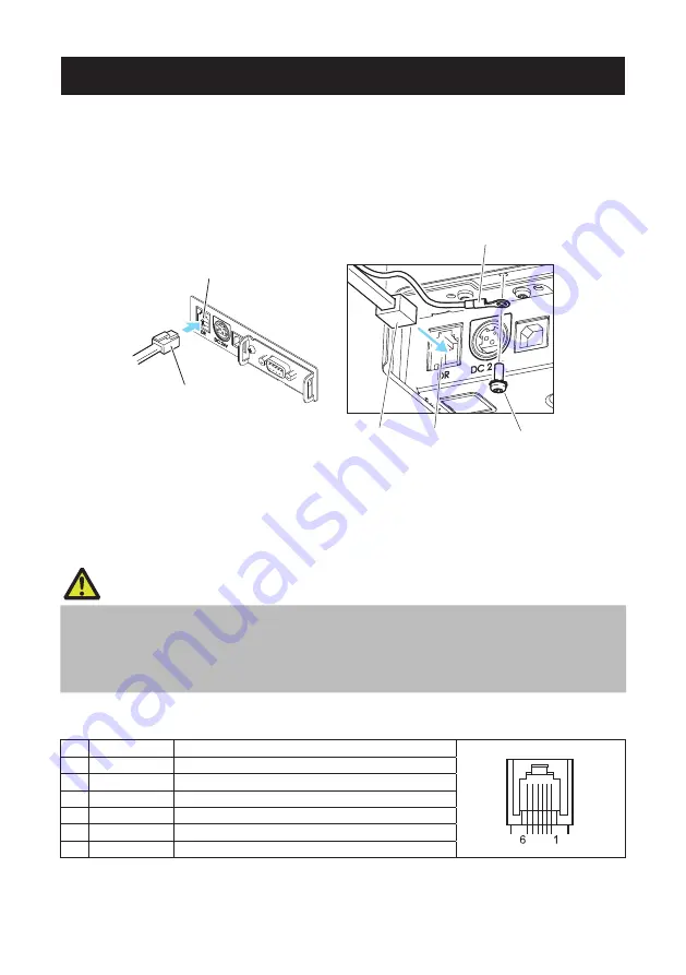
3.5 Connecting the Cash Drawer
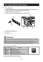
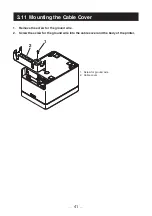
1. Turn off the power.
2. Confirm the orientation of the cash drawer kick-out cable connector and connect it to
the cash drawer kick-out connector at the back of the printer.
3. Remove the screw for the ground wire.
4. Screw the cash drawer’s ground wire to the body of the printer.
2
1
2
1
4
3
1. Cash drawer kick-out connector
2. Cash drawer kick-out cable connector
3. Ground wire
4. Screw for ground wire
CAUTION
Connect only the cash drawer kick-out cable to this connector. (Do not connect a telephone
line.)
Signals cannot be output from the cash drawer kick-out connector while printing.
Hold the connector of the drawer kick cable perpendicular and straight when connecting or
disconnecting it. Doing it at an angle may cause the connector to misconnect.
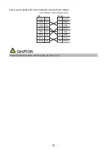
(1) Connector pin configuration
No.
Signal
Function
1
FG
Frame ground
2
DRAWER1
Cash drawer 1 drive signal
3
DRSW
Cash drawer switch input
4
VDR
Cash drawer drive power supply
5
DRAWER2
Cash drawer 2 drive signal
6
GND
Signal ground (common ground on circuits)
Connector used:TM5RJ3-66 (Hirose) or equivalent
Applicable connector: TM3P-66P (Hirose) or equivalent
Summary of Contents for CT-E651
Page 4: ...4 ENGLISH...
Page 50: ...50 5 OTHER 5 1 External Views and Dimensions Unit mm 125 165 108...
Page 57: ...57 FRAN AIS...
Page 104: ...104 5 DIVERS 5 1 Vues et dimensions externes Unit mm 125 165 108...
Page 111: ...111 DEUTSCH...
Page 158: ...158 5 SONSTIGES 5 1 u ere Ansicht und Abmessungen Einheit mm 125 165 108...
Page 165: ...165 ITALIANO...
Page 212: ...212 5 ALTRO 5 1 Viste e dimensioni esterne Unit mm 125 165 108...
Page 219: ...219 ESPA OL...
Page 266: ...266 5 OTROS 5 1 Vistas externas y dimensiones Unidad mm 125 165 108...

