background image

— 34 —

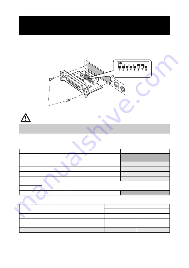
1.

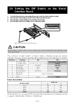
Turn off the printer and unplug the power cord from the electric outlet.

2.

Remove the mounting screws of the serial interface board.

3.

Remove the serial interface board from the printer.

4.

Set the DIP switch according to the following table.

The function of each switch is shown below. (Shaded values are factory
settings. However, factory settings differ depending on the destination market.)

Baud rate selection

When switch no. 1 is set to OFF, you can use a command or a memory switch
to select 1200, 38400, 57600, or 115200 bps.

3.9 Setting the DIP Switch on the Serial

Interface Board

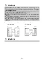
CAUTION

When setting the DIP switch, do not remove any screws except the serial interface board
mounting screws.

Switch no.

Function

ON

OFF

1

Communication 
condition setting

According to DIP switch settings

According to memory switch 

settings

2

Hand shake

XON/XOFF

DTR/DSR

3

Bit length

7 bits

8 bits

4

Parity check

Yes

No

5

Parity selection

Even parity

Odd parity

6

Baud rate 
selection

Refer to table below.

7

8

INIT

Reset

Invalid

Baud rate (bps)

Switch no.

6

7

2400

OFF

OFF

4800

ON

OFF

9600

OFF

ON

19200

ON

ON

DIP switch

Serial interface board mounting screws

Summary of Contents for CT-S651 Type II

Page 1: ...LINE THERMAL PRINTER MODEL CT S651 Type II User s Manual ...

Page 2: ...rodotti elettronici usati in conformità alla legislazione RAEE Direttiva 2002 96 CE valida solo all interno dell Unione Europea It Deponeer dit product niet bij het gewone huishoudelijk afval wanneer u het wilt verwijderen Er bestaat ingevolge de WEEE richtlijn Richtlijn 2002 96 EG een speciaal wettelijk voorgeschreven verzamelsysteem voor gebruikte elektronische producten welk alleen geldt binnen...

Page 3: ... interference in which case the user at his own expense will be required to take whatever measures may be necessary to correct the interference CAUTION Use shielded cable for this equipment Sicherheitshinweis Die Steckdose zum Anschluß dieses Druckers muß nahe dem Gerät angebracht und leicht zugänglich sein For Uses in Canada This Class A Information Technology Equipment ITE complies with Canadian...

Page 4: ...sed by accidents repairs tests or other occurrences If you find omissions errors or have questions please contact your Citizen Systems dealer If you find any pages missing or out of order contact your Citizen Systems dealer for a replacement Made for iPod Made for iPhone and Made for iPad mean that an electronic accessory has been designed to connect specifically to iPod iPhone or iPad respectivel...

Page 5: ...d occur if the printer is improperly operated by ignoring the instructions indicated by the warning symbols SAFETY PRECAUTIONS WHICH SHOULD BE STRICTLY OBSERVED WARNING Neglecting precautions indicated by this symbol may result in fatal or serious injury CAUTION Neglecting precautions indicated by this symbol may result in injury or damage to property This symbol is used to alert your attention to...

Page 6: ...de or any other chemical liquid over the printer Dropping a metallic foreign object into the printer may cause printer failure fire or electric shock Should it occur immediately turn the printer off unplug it from the supply outlet and call your local Citizen Systems dealer Do not handle the printer in the following ways Do not subject the printer to strong impacts or hard jolts e g being stepped ...

Page 7: ...rite cores or other anti noise devices Avoid using the printer with a device that is a strong source of noise The printer may have an adverse effect on nearby radio or TV transmissions There may also be cases when nearby electrical appliances adversely influence the printer causing data errors or malfunction Installed in any orientation other than those specified Malfunction failure or electric sh...

Page 8: ...fire or the circuit breaker to trip Do not allow anything to rest on the power cord Do not place the printer where the power cord may be stepped on Do not use or carry the printer with its power cord bent twisted or pulled Do not attempt to modify the power cord unnecessarily Do not place the power cord near any heating device Neglecting these cautions may cause wires or insulation to break which ...

Page 9: ...Avoid using torn pieces of paper or paper spliced with plastic adhesive tape Avoid forcibly pulling already loaded paper by hand Avoid using a sharp pointed device to operate panel buttons Be sure to firmly insert the cable plugs into their mating sockets A cross connection may damage the printer s internal electronics or the host system s hardware Only use the printer with devices that have desig...

Page 10: ...wing precautions for daily maintenance When cleaning the printer always turn it off and unplug it from the electric outlet Use a soft dry cloth for cleaning the surface of the printer case For severe stains use a soft cloth slightly dampened with water Never use organic cleaning solvent such as alcohol paint thinner trichloroethylene benzene or ketone Never use a chemically processed cleaning clot...

Page 11: ... 9 Setting the DIP Switch on the Serial Interface Board 34 3 10 Adjusting the Paper Near end Sensor 35 3 11 Loading Paper 36 3 12 Attaching the Power Switch Cover 37 3 13 Attaching the Interface Cover 38 3 14 Removing the Interface Cover 38 3 15 Installing a Driver 39 3 16 Precautions for Creating Applications and Practical Operations 39 4 MAINTENANCE AND TROUBLESHOOTING 40 4 1 Periodic Cleaning 4...

Page 12: ...h either 3 inch 83 80 mm or 2 inch 60 58 mm wide paper rolls Built in power supply or AC adapter types available Printer status and errors indicated by LED and a buzzer Equipped with a fast and quiet cutter Easy to clear cutter jams Interchangeable interface Built in cash drawer kick out interface USB power supply OFF Memory switches make customization possible Store user defined characters and lo...

Page 13: ...51IIS Built in power supply type 36AD3 37AD3 AC adapter built in AC power cord Power switch cover USB cable Quick Start Guide CT S651IIA AC adapter type AC adapter 36AD2 37AD5 AC power cord Quick Start Guide CD ROM USB cable Sample paper roll Interface cover Interface cover CD ROM Sample paper roll Power switch cover CT S651IIS 3 RS E BK P Power supply DC No power source S Built in power supply ty...

Page 14: ...er roll Paper roll 83 mm 80 mm 60 mm 58 mm maximum 83 mm Paper thickness 65 75 m core tube diameter inner 12 mm outer 18 mm 75 85 m core tube diameter inner 25 4 mm outer 32 mm Interface Serial RS 232C compliant parallel IEEE 1284 compliant USB USB with hub Ethernet Powered USB Bluetooth 3 0 wireless LAN 802 11b g or 802 11a b g n Cash drawer kick out Supports 2 cash drawers Buffer size 4 k bytes ...

Page 15: ...36AD3 37AD3 is the AC adapter built in to the CT S651IIS 5 Compliant if the Citizen Systems AC adapter 36AD2 3 37AD3 5 is used Names of parts Paper cover Open to load paper Cover open button Use this button to open the paper cover Front cover Open and close this cover to clear a cutter lock Front cover release button Press this button to open the front cover Power switch Press this switch to turn ...

Page 16: ...hes if the print head is hot the paper cover is open a cutter lock occurs and so forth FEED button Press this button to feed paper In case of a cutter lock remove the cause of the lock close the paper cover and then press the FEED button The printer enters the mode for setting memory switches and running self test Refer to 4 4 Self test Refer to 4 6 Error Messages Refer to 5 3 Manual Setting of Me...

Page 17: ...tch Cash drawer kick out connector Connects to the cable from the cash drawer Power connector AC adapter type Connects to the AC adapter cable AC inlet built in power supply type Connects to the AC power cord Interface connector serial parallel USB etc Cash drawer kick out connector Power connector AC adapter type AC inlet built in power supply type ...

Page 18: ...r end sensor to match the paper being used Manual cutter For cutting the paper manually when printing is finished Auto cutter Automatically cuts the paper when printing is finished Print head thermal Prints characters and graphic data on paper paper rolls 2 2 Inside the Paper Cover Refer to 3 10 Adjusting the Paper Near end Sensor Refer to 5 3 Manual Setting of Memory Switches Platen Button to cha...

Page 19: ...This mode is canceled when the PC is turned back on or when a USB connection is established Paper saving functions Memory switches MSW8 3 through MSW8 5 can be used to configure the settings below which save paper Top margin suppression The printer back feeds the paper before printing which reduces the blank space at the top edge of the paper The back feed amount can be specified Line gap reduce A...

Page 20: ... cause the cut paper to be torn off by the next print operation which can cause printer trouble Note the following precautions when using text compression Compressed text is more difficult to read than the original text Horizontally compressing text also makes the print range smaller so the number of print lines does not change Pay close attention to the print range when using narrow paper Do not ...

Page 21: ... power source that does not also supply power to equipment that generates electromagnetic noise Pulling on the AC power cord may damage it cause a fire electric shock or break a wire If a lightning storm is approaching unplug the AC power cord from the electric outlet A lightning strike may cause a fire or electric shock Keep the AC power cord away from heat generating appliances The insulation on...

Page 22: ...correctly and insert it into the interface connector 3 2 Connecting Interface Cables 10 100BASE Serial interface Parallel interface USB interface hub type USB interface Ethernet interface Powered USB interface Front view Pin Bluetooth USB Wireless LAN LAN ...

Page 23: ...onnector Be careful not to insert the USB interface cable into the cash drawer kick out connector To connect more than one printer to a single computer via a USB interface you must change the serial number of the USB interface Hold the connector of the Ethernet interface cable perpendicular and straight when connecting or disconnecting it Doing it at an angle may cause the connector to misconnect ...

Page 24: ...m among the detected devices Note You can search for devices and change the names When memory switch MSW13 5 is set to No Response nothing is displayed by device detection You can temporarily switch this setting to device detection detect mode by pushing the switch on the Bluetooth interface board Detect mode is exited when the connection between the host PC is terminated 3 3 Bluetooth Interface B...

Page 25: ...communication a connection between a paired iOS device and the printer is not automatically restored after it is lost However when auto reconnection is enabled the printer tries to reconnect with an iOS device after two way communication is enabled and automatically restores the connection Enabling and disabling auto reconnection To change the setting of this feature the following method is provid...

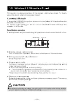
Page 26: ...ered You can use setting mode to read factory settings and to print firmware information If you do not perform any operation for three seconds while in setting mode a buzzer will sound once to indicate the board has returned to normal mode Depending on settings the buzzer may not sound Returning to factory settings Enter the board setting mode and then hold down the panel button This returns the b...

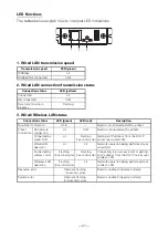
Page 27: ...tion No printer connection Unlit Board is not connected with a printer Connecting with printer Lit Board is connected with a printer No network connection Unlit Board is not connected with a network Getting IP address Flashing 0 5 second cycle Getting an IP address from the DHCP server Connected with network Lit Network connection complete Resource error Alternate flashing 0 5 second cycle Board i...

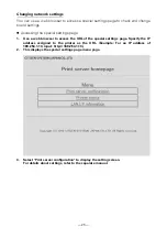
Page 28: ... Use a web browser to access the URL of the special settings page Specify the IP address assigned to the printer as the URL Example For an IP address of 169 254 1 10 input http 169 254 1 10 2 This displays the special settings page menu page 3 Select Print server configuration to display the setting screen For details about settings refer to the separate manual ...

Page 29: ...less LAN setup information Press the panel button Entering setting mode Hold down the panel button A buzzer will sound once to indicate that setting mode has been entered You can use setting mode to read factory settings If you do not perform any operation for three seconds while in setting mode a buzzer will sound once to indicate the board has returned to normal mode Depending on the printer mod...

Page 30: ...rk connection Lit Unlit Board is connected with a printer Connected by wired LAN Lit Flashing 1 second cycle Getting an IP address from the DHCP server over wired LAN Wired LAN operation Lit Lit Network operation being performed over wired LAN Connected by wireless LAN Flashing 2 second cycle Flashing 1 second cycle Connecting to an access point or getting an IP address from the DHCP server over w...

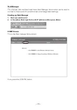
Page 31: ...t can be used to connect to the board with a web browser and change board settings Starting up Web Manager 1 Start up a web browser 2 In the address field input the board s IP address and then press Enter HOME Screen This is the Web manager home screen Here press the CONFIG button ...

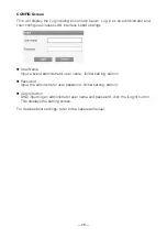
Page 32: ...ce board settings User Name Input a board administrator user name Initial setting admin Password Input the administrator user password Initial setting admin Login button After inputting an administrator user name and password click the Login button This displays the setting screen For details about settings refer to the separate manual ...

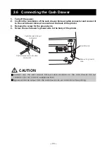
Page 33: ...re 4 Screw the cash drawer s ground wire to the body of the printer 3 6 Connecting the Cash Drawer CAUTION Connect only the cash drawer kick out cable connector to the cash drawer kick out connector Do not connect a telephone line Signals cannot be output from the cash drawer kick out connector while printing Cash drawer kick out connector Cash drawer kick out cable connector Ground wire Screw for...

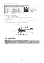
Page 34: ...TM5RJ3 66 Hirose or equivalent Applicable connector TM3P 66P Hirose or equivalent 2 DRAWER1 Cash drawer 1 drive signal 3 DRSW Cash drawer switch input 4 VDR Cash drawer drive power supply 5 DRAWER2 Cash drawer 2 drive signal 6 GND Signal ground common ground on circuits CAUTION Cash drawers 1 and 2 cannot be operated at the same time The solenoid used for the cash drawer should be 24 or more Do no...

Page 35: ... under the following conditions Locations subject to vibration or instability Locations that are very dirty or dusty Locations where the printer is not level The printer may fall and cause an injury The quality of printing may deteriorate Oriented other than as specified The printer may malfunction be damaged or cause an electric shock Horizontal position Vertical position ...

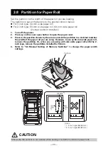
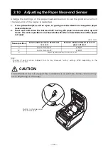
Page 36: ...osition shown by the arrow and set the partition in a slot that matches the width of the paper roll you are using However to use an 83 mm wide paper roll remove the partition Or when you are using a 60 mm wide paper roll with the 2 inch type remove the partition installed for 58 mm 4 Refer to 5 3 Manual Setting of Memory Switches to change the paper width settings 3 8 Partition for Paper Roll CAUT...

Page 37: ...a memory switch to select 1200 38400 57600 or 115200 bps 3 9 Setting the DIP Switch on the Serial Interface Board CAUTION When setting the DIP switch do not remove any screws except the serial interface board mounting screws Switch no Function ON OFF 1 Communication condition setting According to DIP switch settings According to memory switch settings 2 Hand shake XON XOFF DTR DSR 3 Bit length 7 b...
Page 38: ...meters of the paper roll used Note Position of sensor when shipped from factory However factory settings differ depending on the destination market 3 10 Adjusting the Paper Near end Sensor Unit mm Sensor position Exterior diameter when detected as near end Exterior interior diameter of core of paper roll used A Approximately 31 18 12 B Approximately 23 18 12 C Paper near end sensor function is off...

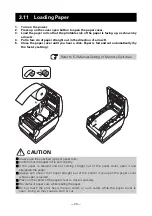
Page 39: ...o 5 3 Manual Setting of Memory Switches CAUTION Always use the specified types of paper rolls Confirm that the paper roll is set correctly If the paper is skewed and not coming straight out of the paper cover open it and straighten the paper Always pull a few cm of paper straight out of the printer if you open the paper cover while paper is loaded Press on the center of the paper cover to close it...

Page 40: ...from being used 1 Press the power switch cover onto the power switch compartment until it clicks Put a screwdriver or other pointed object into the grooves on the power switch cover to remove it 3 12 Attaching the Power Switch Cover Power switch cover ...

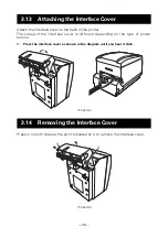
Page 41: ...different depending on the type of power source 1 Press the interface cover as shown in the diagram until you hear it click Press in on both sides at the point indicated by A to remove the interface cover 3 13 Attaching the Interface Cover 3 14 Removing the Interface Cover CT S651IIS CT S651IIS ...

Page 42: ...ut and torn off the top of the next print out may be distorted We recommend advancing the paper one line after cutting before printing If you are using a serial interface that has a slow data transmission speed streaks may appear in the printouts when you are printing graphics or gradated text which require large amounts of data USB interfaces may be susceptible to the effects of electromagnetic i...

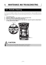
Page 43: ...er open button to open the paper cover 3 Wait a few minutes until the print head cools 4 Use a cotton swab dampened with ethyl alcohol to wipe off any dirt and dust that is on the print head and platen 4 MAINTENANCE AND TROUBLESHOOTING 4 1 Periodic Cleaning CAUTION The print head is hot immediately after printing Do not touch it Do not touch the print head with bare hands or metal objects Platen P...

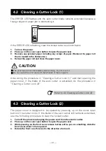
Page 44: ...re in Clearing a Cutter Lock 2 The paper cover is designed to be opened by pressing up on the cover open button if the cutter locks If the blade of the auto cutter still remains extended use the following procedure to clear the locked cutter 1 Turn off the printer and unplug the power cord from the electric outlet 2 Press up on the cover open button to open the paper cover 3 While pressing on the ...

Page 45: ... it clicks 8 Load a paper roll and close the paper cover 9 Insert the power cord plug into an electric outlet and turn the power on Check that the POWER LED lights CAUTION Before starting to do maintenance work be sure to turn off the printer and unplug the power cord from the electric outlet Be careful not to touch the manual cutter while the front cover is open Be careful not to touch the openin...

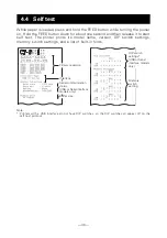
Page 46: ...name version DIP switch settings memory switch settings and a list of built in fonts Note Printers with a USB interface do not have DIP switches so the DIP switches all appear off on the self test printout 4 4 Self test Buffer size Serial communication status USB or Serial interface models only Interface Firmware version Memory switch setting DIP switch settings USB or Serial interface models only...

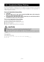
Page 47: ... by the received data printed in hexadecimal numbers and some characters How to stop hexadecimal dump printing Do one of the following to stop printing Press the FEED button three times in a row Turn off the power Receive a reset command from an interface Print example HEX dump print mode 61 62 63 64 65 66 67 0A 0D 0D 0D 0D abcdefg 0D 0D 0D 4 5 Hexadecimal Dump Printing CAUTION The printer prints ...

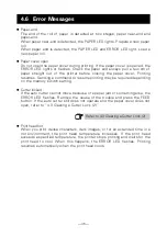
Page 48: ... may be required depending on the memory switch setting Cutter locked If the auto cutter cannot move because of a paper jam or something else the ERROR LED flashes Remove the cause of the trouble and press the FEED button If the auto cutter still does not operate and the paper cover does not open refer to 4 3 Clearing a Cutter Lock 2 Print head hot When you print dense characters dark images or fo...

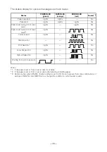
Page 49: ...tions of settings of MSW5 1 and MSW10 6 may change the condition in which buzzer sounds Status POWER LED green PAPER LED orange ERROR LED red Buzzer 3 Paper near end Lights Lights No Paper end Lights Lights Lights Yes Paper cover open or front cover open 1 Lights Lights Yes Paper cover open or front cover open 2 Lights Yes Cutter locked Lights Yes Memory error Yes Print head hot Lights No Low volt...

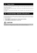
Page 50: ... the serial interface certain printing conditions can cause white stripes in printouts and feed failure To avoid these problems change memory switch settings as described below 1 Change MSW7 1 serial baud rate to a faster baud rate setting 2 Change MSW10 2 print speed to a lower level 4 7 Paper Jams 4 8 Serial Interface Operation Precautions CAUTION Depending on the serial interface transmission s...

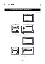
Page 51: ... 48 Unit mm 5 OTHER 5 1 External Views and Dimensions Built in power supply type AC adapter type 192 31 145 140 155 16 142 192 31 145 114 ...

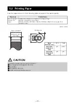
Page 52: ...m Ohji Paper P220AG HP220A HP220AB 1 F230AA P220AB or PB670 2 color paper from Mitsubishi Paper CAUTION Use thermal paper that is wound as follows Not creased and fits tight to the core Not folded Not glued to the core Rolled with the printable side out Printable side 83 or less Paper width 58 0 1 Paper thickness m 53 75 75 85 Core inner diameter d mm 12 25 4 Core outer diameter D mm 18 32 Maximum...

Page 53: ...tton three times and close the paper cover The printer enters memory switch quick setting mode The selectable item Manufacturer and the selection are printed 4 Press the FEED button A selection is printed in order through the cycle each time the FEED button is pressed Press the FEED button until the selection you want is printed 5 Press the FEED button for at least two seconds The selection is set...

Page 54: ... FEED button is pressed Press the FEED button until the number for the memory switch you want to change is printed Selected item Automatic memory switch settings Manufacturer Model Paper width Character space MSW2 4 Full Col Print MSW3 7 CBM1000 Mode MSW8 1 Print Width MSW6 2 Character Space CITIZEN CBM1000 58 mm Auto linefeed Valid 432dots 80 mm Auto linefeed Valid 576dots CT S300 58 mm WaitData ...

Page 55: ...at steps 5 to 7 to change different functions for the current memory switch number 9 Open the paper cover and close it The changed memory switch settings are printed 10 Repeat steps 4 to 9 to change functions for a different memory switch number 11 Press the FEED button until Save To Memory is printed 12 Press the FEED button for at least two seconds The changed memory switch settings are saved an...

Page 56: ...SW2 6 Reserved Fixed MSW2 7 Reserved Fixed MSW2 8 PNE Sensor Valid Invalid MSW3 1 Resume Cttr Err Valid Invalid MSW3 2 PE signal by PNE Valid Invalid MSW3 3 Parallel 31 Pin Valid Invalid MSW3 4 Reserved Fixed MSW3 5 Reserved Fixed MSW3 6 Reserved Fixed MSW3 7 CBM1000 Mode Invalid Valid MSW3 8 Resume Open Err Close Command MSW4 1 Reserved Fixed MSW4 2 Reserved Fixed MSW4 3 Feed Cut at TOF Invalid V...

Page 57: ... 10mm 11mm MSW8 4 Line Gap Reduce Invalid Invalid 3 4 2 3 1 2 1 3 1 4 1 5 ALL MSW8 5 Reduced Char V H 100 100 100 100 75 100 50 100 100 75 75 75 50 75 MSW8 6 Auto Side Shift Invalid Invalid 1 dots 2 dots 3 dots 4 dots 5 dots 6 dots 7 dots MSW8 7 Liner Free Mode Invalid Invalid 1h 6h 12h 18h 24h 5m 10m 15m 20m 30m MSW9 1 Code Page PC 437 PC 437 Katakana PC 850 PC 858 PC 860 PC 863 PC 865 PC 852 PC ...

Page 58: ...nsmission speed to prevent the motor from stopping 2 The values for memory switches MSW7 X are only effective when DIP switch no 1 is set to OFF MSW10 4 Old Command Invalid Invalid CBM1 CBM2 MSW10 5 Buzzer Event Not by C Open All Event Error Not by C Open Not by C Open PE MSW10 6 Buzzer Sound Tone 2 Tone 1 Tone 2 Tone 3 Tone 4 MSW13 1 Security Target Low All Low All Mid All Mid Paired only Hi All ...

Page 59: ...CT S651II_UM_110EN A10580E 1610 October 2016 ...

Reviews: