19
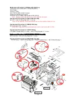
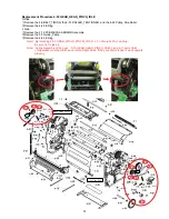
Replacement Procedure 2-30 Ribbon Winding Assy
①
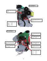
Connector of one place (refer to Wiring Diagram 2)
②
2-6 Springs
③
E Ring 1 place
④
2-3 PLATE_HEAD_Holder 2 screws
⑤
Slide the Head Assy to the right.
⑥
Remove the 2-30 Ribbon Winding Assy while rotating.
Note
)
Rotating metal parts that are in contact should be lubricated.
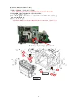
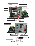
Replacement Procedure 2-35 Main PCB Assembly
Each FFC
(
refer to Wiring Diagram 2
)
4 screws
Note
)
When replacing, the various adjustments must be performed (refer to Ch.4)
Replacement Procedure 2-10 DRIVE PCB Assy
Each connector, FFC
5 screws
Note) When replacing, the various adjustments must be performed (refer to Ch.4)
Replacement Procedure 2-13 LED PCB Assy
FFC(Main PCB Assembly) of 1 place
(
refer to Wiring Diagram 2
)
1 screw.
Replacement Procedure 2-12PCB MECHA SENSOR Assembly
Each connector
(
refer to Wiring Diagram 6
)
1 screw.
Replacement Procedure 2-33 RFID PCB Assembly
FFC of 1 place
(
refer to Wiring Diagram 3
)
Detach it with the hook.
(
refer to Detail drawing 1
)
M
M
Mecha Assy
Flame Assy
[S]
[S]


