background image

 Contents


Introduction ............................................................................................................................................................................................2


For Safe Use ...........................................................................................................................................................................................2


General Warnings...................................................................................................................................................................................5


Chapter 1


Cleaning ..................................................................................................................................................... 8


Alcohol that can be used for cleaning .................................................................................................................................................8


Cleaning the Platen Roller.....................................................................................................................................................................8


Cleaning the Grip Roller and Pinch Roller...........................................................................................................................................9


Cleaning the thermal head ..................................................................................................................................................................10


Chapter 2 Disassembly

Reassembly ......................................................................................................................... 11


Fasten Screw Torque List.................................................................................................................................................................... 11


Maintenance parts ................................................................................................................................................................................12


Applying Grease...................................................................................................................................................................................12


, Disassembly,


Assembly


(Outer cover) ....................................................................................................................................13


, Disassembly

assembly

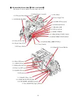
Printer mechanism

........................................................................................................................14


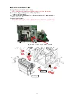
Replacement Procedure 2-32 Thermal Print Head Assembly.............................................................. 15


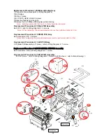
Replacement Procedure Mecha Assy ..................................................................................................... 17


Replacement Procedure 2-29 Head Frame Assembly........................................................................... 18


Replacement Procedure 2-30 Ribbon Winding Assy ............................................................................. 19


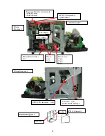
Replacement Procedure 2-35 Main PCB Assembly .............................................................................. 19


Replacement Procedure 2-10 DRIVE PCB Assy ................................................................................... 19


Replacement Procedure 2-13 LED PCB Assy ....................................................................................... 19


Replacement Procedure 2-33 RFID PCB Assembly.............................................................................. 19


, Disassembly

Assembly

Frame Assy

....................................................................................................................................21


Replacement Procedure DAMPER ........................................................................................................ 21


Replacement Procedure 3-38 Inter Lock SW Assy................................................................................ 21


Replacement Procedure 3-40 Fan Motor ............................................................................................... 21


Replacement Procedure 3-32 Power Supply Unit................................................................................. 21


, Disassembly, Assembly

Mechanical Assy

.............................................................................................................................22


Replacement Procedure 4-68 Auto Cutter Unit .................................................................................... 22


Replacement Procedure 4-9 BELT_TIMING ........................................................................................ 22


Replacement Procedure 4-33 ROLLER_PLATEN ................................................................................ 22


Replacement Procedure 4-71 ROLLER_GRIP ...................................................................................... 23


Replacement Procedure 4-32 ROLLER_PINCH................................................................................... 24


Replacement Procedure 4-53 GEAR_HEAD_PINCH_IDLE................................................................ 25


Replacement Procedure 4-55 GEAR_ROLL_REDUCTION_3 ............................................................. 26


Replacement Procedure 4-57 Gear,Cassette ......................................................................................... 26


Replacement Procedure 4-56 Torque Limiter ....................................................................................... 26


Replacement Procedure 4-25 Metal Bearing

d6-D10

..................................................................... 26


Replacement Procedure 4-22 Pulley,Grip Roller................................................................................... 26


Replacement Procedure 4-63 Humidity Sensor Module....................................................................... 27


Replacement Procedure 4-64 Paper Sensor PCB.................................................................................. 27


Replacement Procedure 4-66Paper Guide Assy .................................................................................... 28


Replacement Procedure 4-65 Sensor Plate Assy................................................................................... 29


, Disassemble

Assemble

Mechanical frame L Assy

.............................................................................................................31


Replacement Procedure Assembly,DRUM_Supply_Ribbon ................................................................. 32


Replacement Procedure 5-15 GEAR_HEAD_PINCH_CAM_L ............................................................ 32


Replacement Procedure 5-16 Gear_Supply_Tension ............................................................................ 32


Replacement Procedure 5-33 SA,Holder_Ribbon_LT ........................................................................... 32


Replacement Procedure 5-32 SA,Holder_Ribbon_L ............................................................................. 32


Replacement Procedure 5-19 HeadUP_Worm_Gear............................................................................. 32


Replacement Procedure 5-24 Motor Assy.............................................................................................. 32


Replacement Procedure 5-25 Step_Motor_PM25L ............................................................................... 32


Replacement Procedure 5-20 Bearing(d6-D12)..................................................................................... 32


Summary of Contents for OP900II

Page 1: ...D DI IG GI IT TA AL L P PH HO OT TO O P PR RI IN NT TE ER R Technical Manual OP900II Version 1 00...

Page 2: ...ublished Other Cautions There may be discrepancies in the contents of this manual due to changes in unit specifications The explanatory illustrations and pictures in this manual are meant to assist in...

Page 3: ...hem Regarding Warning and Caution Listed below are foreseeable results of misuse of the printer which have been classified as Warning or Caution depending on the level of danger and the possibility of...

Page 4: ...damage with the edges of the device The printer weighs approx 14kg When moving it be careful to lift it so as not to cause physical injury Lifting carelessly or recklessly could cause it to drop resu...

Page 5: ...uld cause discoloration At least once a year unplug the printer and remove any dust from between the prongs Accumulation of dust could cause a fire When using continuously for long periods of time in...

Page 6: ...l iron particles trash dust Do not spill liquids or spray chemicals on the device Do not step on drop or strike the printer or otherwise apply strong pressure or shocks Be careful not to hurt yourself...

Page 7: ...y Mechanical Assy 22 Replacement Procedure 4 68 Auto Cutter Unit 22 Replacement Procedure 4 9 BELT_TIMING 22 Replacement Procedure 4 33 ROLLER_PLATEN 22 Replacement Procedure 4 71 ROLLER_GRIP 23 Repla...

Page 8: ...tage Adjustment 48 3 Mechanism Adjustments 52 4 Thermal Print Head Settings 54 5 Driver board setting 55 6 Checking and Setting the Serial Number 56 7 Rewriting Firmware and CWD Control Data 57 8 Adju...

Page 9: ...on the prints please clean the platen roller There could be powder paper scraps or other grime from the ribbon etc on the platen roller 1 Use gauze or some other soft cloth moistened with ethyl alcoh...

Page 10: ...t the paper with the double sided sticky tape facing up Turn the cam in the direction of the arrow and align the hash mark with the metal edge So the media can be advanced Caution Hash mark with the m...

Page 11: ...a piece of gauze or other soft cloth soaked in alcohol 2 Wipe the thermal print head gently without touching the thermal print head by the direct hand 3 When dirt cannot be removed it wipes about fiv...

Page 12: ...0 05N 2 21 3 35 4 40 Pan Head Screw SMP 4 5 SemsW 1 05 0 05N 5 26 6 23 Pan Head Screw SMP 3 5 SemsA 0 8 0 05N 2 20 Pan Head Screw SMP 3 24 SemsA 0 30 0 05N 1 15 Binding Head Screw SMB 3 5 Ni 0 65 0 05...

Page 13: ...ll maintenance parts are prepared by customer side If you want parts with mark you can purchase from us PARTS No DESCRIPTION JW 99055 00F Silicone grease 80g Shin Etsu Chemical G501 JW 99115 00F Sunli...

Page 14: ...ont hook of 1 place and lift it 1 24 Case_side_L 3 screws Remove the front hook of 1 place and lift it 1 26 Case_upper 1 screw Front hook 1 6 PLATE_REAR 6 screws The part USB use binding head screw Th...

Page 15: ...2 33 RFID PCB Assembly 3 38 Inter Lock SW Assy 3 40 Fan Motor 3 32 Power Supply Unit 4 68 Auto Cutter Unit 4 9 BELT_TIMING 4 33 ROLLER_PLATEN 4 71 ROLLER_GRIP 4 32 ROLLER_PINCH 4 53 GEAR_HEAD_PINCH_I...

Page 16: ...rmal Print Head Assembly Replace 2 32 Thermal Print Head Assembly Note Torque 0 30 0 05N m If the screw torque is incorrect it could be detrimental to print quality When installing the Thermal Print H...

Page 17: ...dge Pass two harness piled up through the core Core is two Pass the harness through the guide FFC 28pin repeats same procedure as FFC22PIN FFC28PIN Fix the core into the hook Notes when attaching the...

Page 18: ...n 3 connectors Plug out Harness from 2 25 Locking Clamp refer to the figure below 2 1 2 27 with right and left each screw Lubricate the point of shaft when replacing 2 21 Ground 1 screw M4 Remove the...

Page 19: ...Note When the spring is removed the Mecha Assy could drop Use caution Slide the Head Assy right and lift it up Note Note Be careful of the Ribbon Rewind Assy gear when sliding it Note When replacing t...

Page 20: ...Note When replacing the various adjustments must be performed refer to Ch 4 Replacement Procedure 2 10 DRIVE PCB Assy Each connector FFC 5 screws Note When replacing the various adjustments must be p...

Page 21: ...B Assembly 7pin Mecha Assy 14pin 12pin 6pin Head Assy 10pin Ribbon Rewind Assy 5pin FFC 26pin FFC 28pin Thermal Print Head Assembly 28pin 470mm 26pin 505mm RFID PCB Assembly 7pin 500mm LED PCB ASSY 2...

Page 22: ...not to damage the hook Replacement Procedure 3 40 Fan Motor 1 connector refer to the figure below 2 screws Screw torque 0 74 0 05N m Note Take note of the fan direction Affix it so it blows into the...

Page 23: ...and cut position refer to Ch 4 Replacement Procedure 4 9 BELT_TIMING Loosen the 4 50 PLATE_TENSIONER screw Note The belt tension is set correctly with 4 6 spring_tension Be sure not to move it when l...

Page 24: ...out so beware of injury or damage 4 4 Grip Roller Spring 4 43 Spacer_Grip_Spring Remove the 4 29 Bearing d8 D14 F Pull the 4 71 ROLLER_GRIP Note There are numerous bumps on the roller to help feed th...

Page 25: ..._GRIP Remove the 4 46 E Ring and the 4 26 Bush Remove the 6 1 Plate_Pinch_Up_R with E Ring Remove the 4 32 ROLLER_PINCH and 4 30 Bearing d6 D12 F Note By removing 5 4 and 6 1 the ROLLER could drop so...

Page 26: ...B MECHA SENSOR Assembly Remove the 5 7 Guide_Cable Remove the 4 45 E Ring Note By removing 4 53 GEAR_HEAD_PINCH_IDLE 4 10 Straight Pin can drop Be sure not to lose it Note During Assembly of the gear...

Page 27: ...45 E Ring Replacement Procedure 4 56 Torque Limiter It can be removed by removing 4 57 Gear Cassette Note 4 52 Straight Pin can drop Be sure not to lose it Replacement Procedure 4 25 Metal Bearing d6...

Page 28: ...uch force on the hook can damage it Replacement Procedure 4 64 Paper Sensor PCB Connector 1 place refer to Wiring Diagram 6 4 23 cover_cable is assembled with the hook Note Putting too much force on t...

Page 29: ...t at 4 33 4 71 4 15 4 32 4 14 4 12 4 13 4 53 GEAR_HEAD_PINCH_IDLE 4 5 Spring_Mecha_Open 4 23 cover_cable Please remove the parts respectively Mecha Frame R Assy Mecha Frame L Assy The parts can be rem...

Page 30: ...shaft at 4 33 4 71 4 15 4 32 4 14 4 12 4 13 4 53 GEAR_HEAD_PINCH_IDLE 4 5 Spring_Mecha_Open 4 23 cover_cable Please remove the parts respectively Mecha Frame R Assy Mecha Frame L Assy The parts can be...

Page 31: ...Wiring Harness 4pin 4 63 4 66 Paper Guide Assy 3pin 4 59 Wiring Harness 2pin 5 24 4pin 5 25 6pin 2 10 4 64 Paper Sensor PCB 2pin 4 65 Sensor Plate Assy 2pin 3pin Wiring Diagram 5 4 60 Wiring Harness...

Page 32: ...31 Disassemble Assemble Mechanical frame L Assy L S S Inside of cam L M L...

Page 33: ...ly_Ribbon 5 29 E Ring 1 place Replacement Procedure 5 33 SA Holder_Ribbon_LT 5 31 screws 2 place Replacement Procedure 5 32 SA Holder_Ribbon_L 5 31 screws 2 place Replacement Procedure 5 19 HeadUP_Wor...

Page 34: ...33 Disassemble Assemble Mechanical frame R Assy S S S S L L...

Page 35: ...GEAR_HEAD_PINCH_IDLE 4 55 GEAR_ROLL_REDUCTION_3 Please remove parts respectively 4 60 Wiring Harness 6pin refer to Wiring Diagram 5 6 18 HOLDER_CABCLE_B Remove the 6 4 STAY_MAIN_MOTOR the screw from...

Page 36: ...ed there If the Printer Driver is not there you need to install the Driver After installing it reboot the computer 2 Copy the entire OP2 Tools directory this directory to the hard disk 3 To start up t...

Page 37: ...eck that the printer is turned ON 2 Run OP2 Tools32 exe 32bit OS or OP2 Tools64 exe 64bit OS 3 If multiple printers installed on the computer the Please select printer window will appear Select OP900I...

Page 38: ...s is not used Port setting Selects the printer Selection is possible when multiple printers are connected Exit Closes OP2 Tools 1 Port setting If multiple printers installed on the computer the Please...

Page 39: ...heck Displays the printer s color control data version 1 Write All Data CWD This writes the color control data to the printer The file selection dialog box will open Select the CWD Control data to be...

Page 40: ...re version Ribbon Status Displays the current ribbon status Counter quantity remaining Lot No Offset value RFID Tag data Print Sheets Counter Displays the printer s current life counter 1 Printer Stat...

Page 41: ...current ribbon status click on Get 4 Print Sheets Counter To display the Life counter Counter A B and Matte Counter Counter M click on Get To clear the Counter A B click on Clear A or Clear B To clea...

Page 42: ...nter Serial No Displays and writes the serial number Mechanism Adjustment Displays and writes the adjustment values for the print position and cut scrap length Sensor Monitor Displays the voltage and...

Page 43: ...3 Driver Adjustment To display the Driver Adjustment values click on Get Enter the Driver Adjustment value stuck on the driver board and click on Setup The adjustment value will be written to the pri...

Page 44: ...on Setup The adjustment value will be written to the printer Print result Cause Correction Scrap length is shorter than 5 5 Distance from the sensor to the cutter is longer than ideal Increase the Cut...

Page 45: ...en to the printer Print result Cause Correction Remaining print length is less than 0 8 Distance from the sensor to the head is longer than ideal Decrease the Print position adjustment by the length l...

Page 46: ...rent printer voltage temperature and humidity of the internal sensors click on Start 7 Flash rom writer This writes the firmware to the printer The file selection dialog box will open Select the ROM d...

Page 47: ...46 2 4 Window Display Function Cascade Lines up the open Windows 2 5 Help Display Function About Displays the OP2 Tools version...

Page 48: ...embly Ribbon tension unit Head power voltage Sensor voltage Head Rank Setting Head resistance value Heat Rank Head adjust value Print position setting Cut position setting Serial No Firmware CWD data...

Page 49: ...e resistors on the Driver Board Signal Resistor Paper end VR1 Ribbon R VR2 PC Mark VR3 Ribbon C VR4 Head Power Voltage Range 35 0V 0 05V Caution Variable resistor Variable Resistor VR3 PC Mark VR1 Pap...

Page 50: ...Click on Start to start measuring Adjustment ranges When adjusting When checking operation Sensor Name Register Status Value V Status Standard v Paper end VR1 With Paper 0 7 0 05 W O Paper 4 5 or more...

Page 51: ...r should be inserted at the Paper End Sensor location Now adjust resistor VR1 on the Main Board so that the Paper End value on the Sensor Monitor is 0 7 0 05 When checking operation In When checking o...

Page 52: ...an area is over the sensor Use an unused section of ribbon Manually rotate the head up roller so that the shading plate is positioned to block the sensor Adjust each ribbon sensor Slowly rotate the ri...

Page 53: ...re that the end of the paper is parallel with the cutter Print 1 all gray image Then measure the cut scrap from this print Print result Reason Adjustment First cut scrap is shorter than 5 5 mm Distanc...

Page 54: ...ition adjustment adding the amount long Example Enter the value and click the Setup button The setting will be written to the printer The values set to the printer can be checked by clicking Get in th...

Page 55: ...nd click on Setup Click on Get and check the HeadRank head resistance value setting When replacing the Main Board enter the values from the previous board 2 Setting Heat Rank Check the values on the R...

Page 56: ...r the driver board Under the Option menu click on Driver Adjustment Enter the value checked in and click on Setup Click on Get and check the Driver Adj value When replacing the driver boad write the a...

Page 57: ...cing the Main Board get the value and write it down or check the rating plate Turn the printer ON Run OP2 Tools and select the printer to be set Under the Option menu click on Setup of Serial No Enter...

Page 58: ...ansmission will begin and the firmware rewriting will begin When rewriting the firmware the green LED will blink Depending on computer performance the time to data transmission may differ slightly Whe...

Page 59: ...the CWD control data the green LED will blink When rewriting is complete the LED will turn green It is not necessary to reboot the printer Unlike when rewriting firmware the printer does not beep whe...

Page 60: ...tension setting With the power OFF open the printer and adjust the tension by setting the tension adjustment jig and loosening the tension adjustment screw Pull the ribbon at a speed of 1 5 seconds p...

Page 61: ...Set the paper properly and close the front cover Close the front cover LED Display Paper error Ribbon error Head Cooling Thermal Protect Othe system error Power Ribbon Paper Error Solution Free the pa...

Page 62: ...aper Jam Paper Jam Paper supply trouble Ribbon End Ribbon end Ribbon supply trouble Ribbon Error Ribbon sticking Ribbon tear Trouble of ribbon feed Ribbon Tension Error Problem with ribbon tension Hea...

Page 63: ...k the damage of harness Replace harness and driver board Ch 2 2 10 4 60 6 21 Damage of paper feeding motor Replace the motor Ch 2 6 30 Paper feeding motor stopped Faulty main board Replace Ch 2 2 35 F...

Page 64: ...Ch 2 5 25 4 59 Incorrect harness connection Faulty connector App Harness Diagram Faulty driver board Replace Ch 2 2 10 Ribbon feed tension is incorrect Faulty main board Replace Ch 2 2 35 Faulty of s...

Page 65: ...s damaged Ch 2 4 59 Check the connections of FFC Connecting the driver board and the main board Ch 2 2 16 2 17 Faulty driver board Replace Ch 2 2 10 Head position motor is not turning Faulty main boar...

Page 66: ...Diagram Faulty cutter or life cycle Replace the cutter Ch 2 4 68 Faulty sensor board Replace the sensor board Ch 2 2 12 Check the connections of harness connecting the sensor and the sensor board Ch...

Page 67: ...size of the media setting to the printer Set the media ribbon united with the size of sending data User s Manual SYSTEM ERROR Event Cause and Solution Reference Turn off the power supply of the print...

Page 68: ...k detection Head Up Yellow Cyan Magenta OP Feed Margin Cut Feed Cut Print Paper edge detection Feed Pinch Roller Down Pinch Roller UP Head Pinch Roller Ribbon Pinch Roller Paper Paper edge sensor PC m...

Page 69: ...licone on the head FFC Clean the FFC 5 Unprinted area spot There is dirt on the media Clean the inside of the printer There is dirt on the platen rolleror broken P 51mm Clean the platen roller or Repl...

Page 70: ...C Ch ha ap pt te er r 6 6 A Ap pp pe en nd di ix x Information on servicing the printer For questions regarding operation and servicing of the printer contact the dealer where the printer was purchas...

Page 71: ...bonEdgeSensor_Right CN2 PaperEndSensor_LED 3 3VGND PaperEndSensor_LED CN2 3 3V PaperEndSensor_Tr Paper end sensor CN3 3 3V 3 3VGND Paper mark sensor PaperMarkSensor CN4 RibbonLED CN5 3 3V 3 3VGND 3 3V...

Reviews: