background image

28

PRU·PMU·PHU SERIES SPECIFICATIONS

7.3 PHU (Paper Holding Unit)

7.3.1 Loading a Paper Roll

Paper winding

direction

1

Check the winding direction of the paper roll, and then insert the paper roller
into the paper roll.

2

Install the paper roller (on which paper roll was set) in the paper holder.

Paper roller

Summary of Contents for PHU-131

Page 1: ...PRINTER PRESENTER UNIT MODEL PRU PMU PHU Series Rev 1 0 First created Oct 14 1999 Rev 1 1 Revised Jan 25 2000 Specifications...

Page 2: ...y apply to this product 2 The contents of these specifications are subject to change without prior notice Always consult the latest revision of the specifications 3 Transcription duplication or modifi...

Page 3: ...rinter Mechanism Unit 7 2 2 3 PHU Series Paper Holding Unit 7 2 3 Designing PRU and PMU Unit Installation 8 3 CONNECTION TERMINALS 10 3 1 Connection Terminals 10 3 1 1 Presenter s Connection Terminals...

Page 4: ...hanism Unit 24 7 2 1 Loading Printing Paper 24 7 2 2 Removing Residual Paper 26 7 2 3 Clearing Paper Jams 27 7 3 PHU Paper Holding Unit 28 7 3 1 Loading a Paper Roll 28 7 3 2 Paper Near End Sensor Fun...

Page 5: ...y realized at a low cost based on a simple mechanism Up to 170 mm or 6 7 inches long receipts can be issued Receipts longer than 170 mm are pushed out of the paper output slot as printing proceeds Equ...

Page 6: ...near a heater radiator or in direct sunlight Avoid using the equipment in a high temperature high humidity or dirty environment Avoid condensation occurring on or inside the equipment If condensation...

Page 7: ...PRU Series Presenter Unit PRU 130 Composition Paper transport section Auto cutter Paper sensor Attaching bracket 2 1 2 PMU Series Printer Mechanism Unit PMU 231 Composition Printer mechanism Paper gui...

Page 8: ...fe 30 km or over Auto cutter life 500 000 cuts or over Use environment Operation 5 to 40 C 35 to 85 RH no condensation Storage 20 to 60 C 10 to 90 RH no condensation External dimensions Refer to 8 1 O...

Page 9: ...loss PC 75 mW Total allowable loss Ptot 100 mA Operating temperature Topr 20 to 85 C Storage temperature Tstg 40 to 100 C Soldering temperature within 5 sec Tsol 260 C Recommended circuit diagram 4 P...

Page 10: ...tr VCE 2 V I C 100 A 20 100 s charac time Lower limit tf RL 1 k d 1 mm 20 100 s teristics Leakage current ILEAK IF 4 mA VCE 2 V 0 1 A Photoelectric characteristics Recommended circuit diagram For pin...

Page 11: ...eight 0 3 kg External dimensions Refer to 8 2 Outline Drawing for PMU 231 Operating temperature 5 to 40 C 35 to 85 RH no condensation and relative humidity Storage temperature 20 to 60 C 10 to 90 RH n...

Page 12: ...ning PRU and PMU Unit Installation Install the PRU and PMU units by referring to the following dimensions 0 0 81 4 50 28 5 52 12 3 7 5 When paper is longer than 170 mm Detection position of the auto l...

Page 13: ...use M3 tapping screws Exercise good care so that no unnecessary load is applied to the equipment and cables Make sure that there are no obstructing objects when opening closing the PRU front door Avo...

Page 14: ...ctor Molex Drive motor 5 Molex 53014 0510 Paper sensor 51004 0500 53015 0510 53025 0510 Terminal No Terminal name Function 1 Light emitting diode Anode 2 Photo transistor Collector Paper sensor 3 Phot...

Page 15: ...Cutter drive motor Molex Molex Switch 4 5264 04 5267 5268 3 1 2 Auto Cutter s Connection Terminals 1 Connectors Used and their purposes Terminal No Wire color Function 1 Red Motor 2 Black Motor 3 Gray...

Page 16: ...re shown below 1 Cable Connectors used and their purposes Function No of pins Type Recommended mating connector Motor Paper sensor FFC Molex Head up sensor 20 Pitch 1 25 mm 5597 20APB Thermal head 559...

Page 17: ...STRB 1 Strobe 1 8 V cc Thermal head driver power supply 9 TH Thermistor 10 GND GND 11 CP Clock signal for data transfer 12 DO Print data serial output 13 PR For identification of heating element resi...

Page 18: ...Paper sensor 7 Light emitting diode anode 8 Light emitting diode cathode 9 Head up sensor output Head up sensor 10 Head up sensor output 11 COM Thermal head common 12 COM Thermal head common 13 COM T...

Page 19: ...quence and drive sequence refer to the separate Specifications for the ACS 230 Power On Hardware initialization Auto cutter ACS 230F initialization No Waiting for Alarm to be reset Auto loading perfor...

Page 20: ...Full cutting Auto cutter is driven For the ACS 230 initialization sequence and drive sequence refer to the separate Specifications for the ACS 230 Paper outputted from paper exit slot Complete I Auto...

Page 21: ...one of various print commands such as print command OAh print and line feed command ODh print and minimal pitch paper feed command ESC J and print and n line paper feed command ESC d is executed Print...

Page 22: ...of paper blank feed if a paper out condition occurs the auto cutter is not driven and the equipment goes into a wait alarm reset state Full cutting Auto cutter is driven For the ACS 230 initialization...

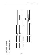
Page 23: ...ATIONS 5 TIMING CHART 5 1 PRU Timing Chart Printer Presenter Auto Cutter Motor Drive Signal ON OFF Motor Drive Signal Motor Drive Signal Motor Brake Signal Cutter Sensor Signal ON ON OFF ON OFF ON OFF...

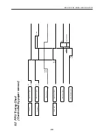
Page 24: ...ming Chart Controlled by paper sensor Printer Presenter Auto Cutter Motor Drive Signal ON OFF Motor Drive Signal Paper Sensor Motor Drive Signal Motor Drive Signal Cutter Sensor Signal ON LOW HIGH ON...

Page 25: ...efer to Sec 2 3 for Designing PRU and PMU Unit Installation 3 Exercise good care so that no unnecessary load is applied to the equipment and cables 4 Make sure that there are no obstructing objects wh...

Page 26: ...1 Turn OFF the power 2 Open the front door 3 While rotating the roller with your hand remove any paper from the inside completely 4 Use a pair of tweezers to remove any paper jamming 5 Close the front...

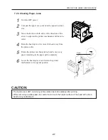
Page 27: ...path 2 Turn ON the power The auto cutter initializes itself and the blade is returned 3 If the blade is not returned by the operation in step 2 turn OFF the power and rotate the auto cutter emergency...

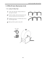
Page 28: ...Paper roller Paper winding direction 1 Cut the edge of the paper roll approximately at a right angle and straight 2 Check the winding direction of the paper roll and then insert the paper roller into...

Page 29: ...lightly to remove the slack If the paper is set inclined raise the head up lever to correct or pull the paper out once and then reinsert it Do not hold or push on the paper while in printing This may...

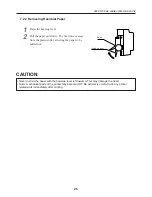
Page 30: ...the head Some mechanical parts of the printer may become HOT Be extremely careful to do any printer related work immediately after printing 7 2 2 Removing Residual Paper Knob Head up lever 1 Raise the...

Page 31: ...per Jams Knob 1 Turn the OFF power 2 Cut apart the paper at a point near the paper insertion slot 3 Move the knobs on both sides in the direction of the arrow to separate the printer mechanism and the...

Page 32: ...olding Unit 7 3 1 Loading a Paper Roll Paper winding direction 1 Check the winding direction of the paper roll and then insert the paper roller into the paper roll 2 Install the paper roller on which...

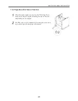
Page 33: ...or Function 1 When the paper supply becomes low the PNE Paper Near End sensor outputs a signal informing the host of this fact and printing can be stopped 2 The PNE sensor can be adjusted by loosening...

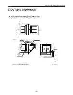
Page 34: ...Drawing for PRU 130 67 Paper roll center Paper roll width Note 1 4 2 7 Burred Paper insertion slot Paper exit slot Auto cutter harness Presenter harness Note 1 Use M3 tapping screws 90 8 52 14 5 46 2...

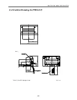
Page 35: ...PRU PMU PHU SERIES SPECIFICATIONS 8 2 Outline Drawing for PMU 231 Flat cables Note 1 Use M3 tapping screws 4 21 68 5 4 2 7 Burred 37 5 5 25 26 5 33 23 49 23 160 1 5 Note 1 66 80 121 3 2 3 Slots Unit...

Page 36: ...32 PRU PMU PHU SERIES SPECIFICATIONS 8 3 Outline Drawing for PHU 131 132 PNE harness 6 5 5 1 6 132 2 122 2 12 203 2 Max paper roll dia 250 48 48 125 2 120 Unit mm...

Reviews: