3- 1
3. Connection and Installation
3-1 Installation of Controller
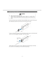
Installation on the 35-mm wide DIN
rail
Fit the hook on the spring side into the DIN rail,
and while pushing it forward, fit the hook on the
fixing side into the DIN rail.
To remove, lift and disengage the hook on the
fixing side whilst pushing in the (fixing side) hook
direction (toward the side on which the top of the
case curves).
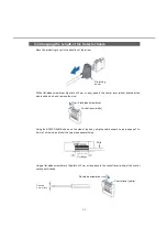
Connecting controllers
1)
Attach the master unit onto the DIN rail.
2)
Remove the connector cover.
3)
Attach each slave unit onto the DIN rail
individually.
Remove the connector cover of the slave
unit, except for the unit at the end.
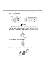
4)
Connect the female connector to the male
connector by sliding the slave unit.
Caution
■
Be sure to turn off the power before connecting slave units to or removing them from the
master unit. Connecting them with the power on may cause damage to the controller.
■
When connecting a male connector into a female connector, press it in firmly as far as it
will go.
Imperfect connection may cause damage to the controller.
■
If connecting two or more units, be sure to attach them onto the DIN rail.
When doing so, attach commercially available end plates at both ends so as to sandwich
the units between them.
■
Up to 15 slave units can be connected to one master unit.
■
When connecting a slave unit to a master unit, these must be of the same output type,
i.e., both NPN-type or both PNP-type. Different output types cannot be connected
together.
End plate
When attaching multiple connected units onto the DIN rail, or when units are not held stable on the DIN
rail, be sure to use commercially available end plates.
■
■
Attach
(1)
(2)
Remove
(2)
(1)
Master unit
Connector
cover
Slave unit
Slide


