background image


Installation and Setup 

Proper installation for convection cooling 

The PDS-375 TRX is designed to be convection cooled, so during normal operation the unit is 
cooled by airflow that occurs naturally due to convection through the Power Supply area.  The 
unit should be operated in its normal upright position (handle up, feet down) with free and 
unrestricted airflow on all sides to assure proper convection cooling.   The unit may either be 
placed on a flat surface on its feet or hung from appropriate user-provided hardware by its 
handle (see below) in the upright position.  Note that the feet are part of the ventilation system 
and must be installed and in good condition if the unit is operated while standing on a flat 
surface.   
 
The PDS-375 TRX is provided with a supplemental fan (located on the bottom of the unit) which 
will turn on automatically if the unit is operated in a position other than the normal upright 
position.  Do not obstruct the fan or block airflow to the fan. 

Mounting the PDS-375 TRX with hanging hardware 

The PDS-375 TRX may be hung with suitable hanging hardware using the two ½” holes 
provided in the Handle.  Do not hang the unit from a single hanging device using only one of the 
two ½” holes, as excessive torque will be placed on the handle. A safety cable hole is provided 
in the Right Side of the unit for use with a user-provided safety cable when the unit is installed 
with hanging hardware. 
 

OPERATING THE PDS-375 TRX 


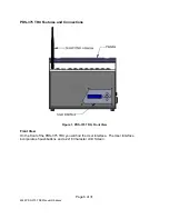
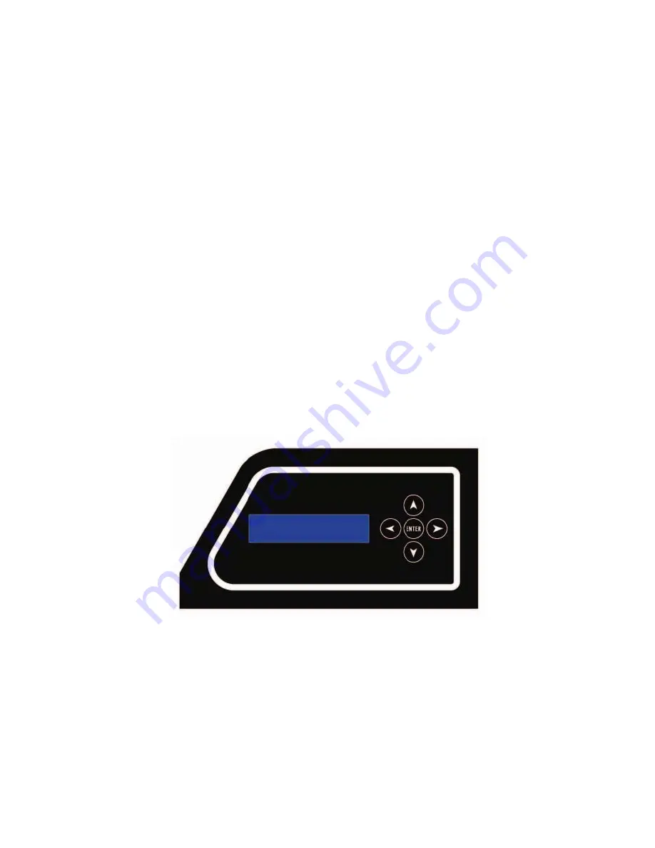
Figure 6, PDS-375 TRX User Interface 

User Interface 

The PDS-375 TRX is provided with a button pad for user control and an LCD screen that 
displays menu settings, configuration options, performance data, and any other text or graphics 
that relate to unit function.   
 
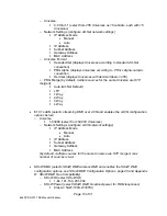
Press the Enter (center) button to access the menus, and press the Up or Down buttons to 
move through the menus. When you reach a menu that you want to work in, simply press Enter 

Page 10 of 31 

6550 PDS-375 TRX Manual R6.docxx 


Summary of Contents for PDS-375 TRX

Page 1: ...The PDS 375 TRX Power Data Supply User s Manual Rev 6 2010 City Theatrical Inc SHoW DMX Transceivers are covered by U S Patent 7 432 803 and other patents pending ...

Page 2: ...PERATING THE PDS 375 TRX 10 User Interface 10 Configuring the PDS 375 TRX 11 Power 11 CKDMX Ports 11 DMX512 Connections 11 Ethernet Connections 11 SHoW DMX Operation 11 USB A Port 11 The Menus 12 PDS 375 TRX Æ main menu 12 The Setup Wizard 12 Input Setup 12 Port Setup 14 Start Addressing 14 Source Selection 14 Personality 14 miniZapi 15 Scene Setup 15 RDM Setup 16 Misc Setup 16 Stand Alone Routine...

Page 3: ... Classic SHoW ID Tables 20 Table 2 Neo SHoW ID Tables 22 Table 3 Neo Adaptive SHoW ID Table 24 Safety Notices Please read this entire manual before using your new equipment Please keep the manual in a safe place so you can refer to it in the future as required The CTI PDS 375 TRX is intended for use only by qualified professionals Connection installation and hanging of this equipment must be perfo...

Page 4: ...ing temperature of PDS 375 TRX 60 of 14 A 8 4 Ampere load There are no user serviceable parts inside Refer to qualified service personnel Aucune maintenance ne doit être effectuée pour les pièces situées dans l appareil Les réparations et la maintenance doivent être executes uniquement par une personne qualifiée RF Exposure The antenna s used for this transmitter must be installed to provide a sep...

Page 5: ... of 2 3 or 5 color fixtures in either 8 or 16 bit mode and patch them without any wasted DMX slots Accepts all Industry Standard Control Protocols You can control your PDS 375 TRX system PDS and fixtures with conventional wired DMX and RDM Wireless DMX and RDM using the built in SHoW DMX receiver Streaming ACN Art Net or Ki Net or with the built in MasterBlast Stand Alone routines Whatever control...

Page 6: ...ons Figure 1 PDS 375 TRX Front View Front View On the front of the PDS 375 TRX you will find the User Interface The User Interface incorporates 5 pushbuttons and a 2x16 Character LCD Screen Page 6 of 31 6550 PDS 375 TRX Manual R6 docxx ...

Page 7: ...The power supply area is on the back of the unit and is covered by the Ventilation Grille The Grille is an active part of the cooling system and must not be obstructed Figure 3 PDS 375 TRX Top View Page 7 of 31 6550 PDS 375 TRX Manual R6 docxx ...

Page 8: ...mware changes and upgrades 2 Ethernet Ports RJ 45 compatible EtherCON 6 CKDMX Ports 4PXLRF In addition the SHoW DMX antenna connection with the included removable 5 dBi omni directional antenna is also located on the top of the unit Figure 4 Left Side View Left Side View The left side contains a hole for use with a safety cable Page 8 of 31 6550 PDS 375 TRX Manual R6 docxx ...

Page 9: ... correct local connector The power cord wire insulation color code is Mains Hot Brown Mains Neutral Blue Safety Earth Ground Green Yellow Color Kinetics CKDMX Output Pinout The PDS 375 TRX CKDMX XLR 4P Output pinout is as follows PIN Signal CK Cable Wire Color Pin 1 24VDC Red Pin 2 n c Pin 3 Data White Pin 4 DC Common Black This pinout matches all Philips Color Kinetics ColorBlast 12 TRX ColorBlas...

Page 10: ... operated in a position other than the normal upright position Do not obstruct the fan or block airflow to the fan Mounting the PDS 375 TRX with hanging hardware The PDS 375 TRX may be hung with suitable hanging hardware using the two holes provided in the Handle Do not hang the unit from a single hanging device using only one of the two holes as excessive torque will be placed on the handle A saf...

Page 11: ...tions Connect a standard 5P XLR DMX Cable to the 5P XLRM DMX input The 5P XLRF Output will function as a standard hard wired DMX pass thru and is auto terminated when no pass thru cable is connected Ethernet Connections Connect the Ethernet source to either etherCON RJ45 Compatible Ethernet port connector The other EtherCON will function as a pass thru port as long as the PDS 375 TRX is operating ...

Page 12: ...8 bit RGBAW 16 bit RGBAW 8 bit RGB5 16 bit or RGB5 8 bit Note fixtures are automatically zapi ed when PERSONALITY is selected to assure correct configuration Base Address Sets the unit s base DMX address and addresses the CKDMX ports sequentially Select any DMX address from 1 512 Universe when Ethernet is selected SHoW ID When SHoW DMX is selected Sets the SHoW ID hopping pattern and bandwidth set...

Page 13: ...Universe are HTP merged Auto Art Net Default LTP 1 Way 2 Way 3 Way 4 Way E1 31 sACN selects streaming DMX over ACN and enables the sACN configuration options below o Universe 1 63999 select from 64 000 Universes o Network Settings configure sACN network settings IP Address Mode Manual Auto IP Address Subnet Address Gateway Address MAC Address by default multiple sources for the same Universe are H...

Page 14: ...ss 1 512 Port 2 Address 1 512 Port 6 Address 1 512 Source Selection Select Universe in Ethernet control methods select a source for the whole unit with All Sources or set individual Sources for each Port with Port 1 Source through Port 6 Source All Sources Port 1 Source Port 2 Source Port 6 Source Personality select a common fixture personality for the whole unit with All Personality or set indivi...

Page 15: ...ode Scene Setup In the Scene Setup menu you can assign any one of the stand alone routines to each of 6 Scenes and then configure the unit to play those Scenes in the order and times you select using the Fade Time and Follow Time settings Fade Time sets the fade time within the routine assigned to the Scene e g the time for a cross fade between colors in Color Wash Follow Time sets the time the Sc...

Page 16: ...oth routines Color 2 R 00 FF G 00 FF B 00 FF Scene 2 as above Scene 3 as above Scene 4 as above Scene 5 as above Scene 6 as above RDM Setup Proxy Enable Enabled Disabled Device Label user entered 32 characters Unique ID factory set Misc Setup Panel Lockout 5 240 seconds Disabled To clear Panel Lockout press and hold the Right and Left Buttons at the same time Backlight T out Always on Always off 1...

Page 17: ...select Enter Button use the Down Button to scroll to Personality and select Enter Button Under All Personality select RGBAW 8 bit Back up to the Setup Menu and scroll to Scene Setup to assign Stand Alone Routines to Scenes 1 6 and configure the Routines selected Set unused Scenes to Disabled Make sure your LED fixtures are either RGB only fixtures TR series or set for RGBAW 8 bit TRX series Fixed ...

Page 18: ...9 etc The effect is of a color spectrum or rainbow moving around the sequentially addressed fixtures The adjustable parameter is the fade rate To adjust the fade rate go to the Color Wave 6 Lgt routine and press Enter A blinking cursor will appear under the fade time Adjust the fade time by pressing the Up and Down buttons Fade time is adjustable between 2 Seconds and 2 hours PDS 375 TRX will cont...

Page 19: ...his show routine is similar to the color wash routine except that color selection is random The adjustable parameter is the fade rate To adjust the fade rate go to the Random Color routine and press Enter A blinking cursor will appear under the fade time Adjust the fade time by pressing the Up and Down buttons Fade time is adjustable between 2 Seconds and 2 hours PDS 375 TRX will continually broad...

Page 20: ...Ds IDs 64 with older power supplies Classic Mode Operation In Classic Mode the SHoW DMX Neo system operates identically to a Classic 5600 series SHoW DMX system and will communicate with 5600 units You can use this mode if you want to combine SHoW DMX Neo and Classic equipment in the same system Classic Mode supports Adjustable Broadcast Power Limited Bandwidth Limited Burst and uses 64 original S...

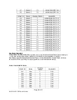
Page 21: ...ed Low Wi Fi 1 6 29 Classic 13 Limited Low Wi Fi 1 6 30 Classic 14 Limited Low Wi Fi 1 6 31 Classic 15 Limited Low Wi Fi 1 6 32 Classic 16 Limited Low Wi Fi 1 6 SHoW ID Mode Hopping Pattern Bandwidth 33 Classic 1 Limited Mid Wi Fi 5 9 34 Classic 2 Limited Mid Wi Fi 5 9 35 Classic 3 Limited Mid Wi Fi 5 9 36 Classic 4 Limited Mid Wi Fi 5 9 37 Classic 5 Limited Mid Wi Fi 5 9 38 Classic 6 Limited Mid ...

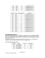
Page 22: ...igh Wi Fi 7 11 60 Classic 12 Limited High Wi Fi 7 11 61 Classic 13 Limited High Wi Fi 7 11 62 Classic 14 Limited High Wi Fi 7 11 63 Classic 15 Limited High Wi Fi 7 11 64 Classic 16 Limited High Wi Fi 7 11 Neo Mode Operation In Neo Mode the SHoW DMX Neo system uses a new broadcast format that reduces latency to 7mS max and provides further resistance to interference susceptibility or creation Neo M...

Page 23: ...125 Neo 9 Limited Low Wi Fi 1 6 126 Neo 10 Limited Low Wi Fi 1 6 127 Neo 11 Limited Low Wi Fi 1 6 128 Neo 12 Limited Low Wi Fi 1 6 129 Neo 13 Limited Low Wi Fi 1 6 130 Neo 14 Limited Low Wi Fi 1 6 131 Neo 15 Limited Low Wi Fi 1 6 132 Neo 16 Limited Low Wi Fi 1 6 SHoW ID Mode Hopping Pattern Bandwidth 133 Neo 1 Limited Mid Wi Fi 5 9 134 Neo 2 Limited Mid Wi Fi 5 9 135 Neo 3 Limited Mid Wi Fi 5 9 13...

Page 24: ... High Wi Fi 7 11 160 Neo 12 Limited High Wi Fi 7 11 161 Neo 13 Limited High Wi Fi 7 11 162 Neo 14 Limited High Wi Fi 7 11 163 Neo 15 Limited High Wi Fi 7 11 164 Neo 16 Limited High Wi Fi 7 11 Neo Adaptive Mode Operation The SHoW DMX Neo system can be configured to operate in the new Neo Adaptive AFHSS Mode Neo Adaptive Mode uses an Adaptive Spread Spectrum Frequency Hopping broadcast format in whi...

Page 25: ...se the Up and Down Buttons to change characters and use the Right and Left buttons to move through the text string Press Enter again to record your label For example if you had PDS 375 TRXs located in front of the DJ Booth you could give them RDM Labels like DJ Booth Left and DJ Booth Right Unique ID The RDM unique ID is factory set and unique for each RDM responder PDS 375 TRX is a fully complian...

Page 26: ...nce with the instructions may cause harmful interference to radio communications However there is no guarantee that interference will not occur in a particular installation If this equipment does cause harmful interference to radio or television reception which can be determined by turning the equipment off and on the user is encouraged to try to correct the interference by one or more of the foll...

Page 27: ...2dBi Nearson DG102N 2 4 5 25 Omni whip SMA plug reverse polarity via provided Antenna Cable 5dBi Centurion WCP2400 MMCX4 Omni whip MMCX jack on 4 coax pigtail 2 5dBi Maxrad MP24008XFPT Panel SMA plug reverse polarity via provided Antenna Cable 8dBi Maxrad MYP24010PT Yagi SMA plug reverse polarity via provided Antenna Cable 10dBi Maxrad MYP24014PT Yagi SMA plug reverse polarity via provided Antenna...

Page 28: ...ming pool Avoid using this product during an electrical storm There may be a remote risk of electric shock from lightning Product Installation and Configuration Guide City Theatrical Inc 2011 Q52 Regulatory information Radio Frequency Notifications Belgique Dans le cas d une utilisation privée à l extérieur d un bâtiment au dessus d un espace public aucun enregistrement n est nécessaire pour une d...

Page 29: ...5792 SHoW DMX Neo Radio CE Declaration of Conformity Page 29 of 31 6550 PDS 375 TRX Manual R6 docxx ...

Page 30: ...n intensity changes Slowest setting Set the fixed color to display in standalone mode by adjusting the intensity of each channel Put the fixture in DMX mode or fixed color mode Set the fixture s color control mode Set the fixture s resolution Set the fixture s dimming curve Set the LED transition speed Display information about the fixture Set the menu unlock time Save current settings as profiles...

Page 31: ...rade Verification Model number on bottom of unit is 6500 Neo SHoW DMX Neo equipped sticker on face of power supply Menu item Misc Firmware Radio Type is Neo CE Available in firmware version 1 3 4 and above Firmware Hardware For power supplies shipped before October 1st 2011 both firmware and radio hardware are require to be compatible with SHoW DMX Neo systems City Theatrical has created an upgrad...

Reviews: