17
10.
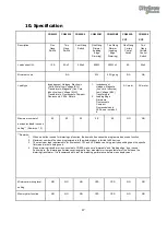
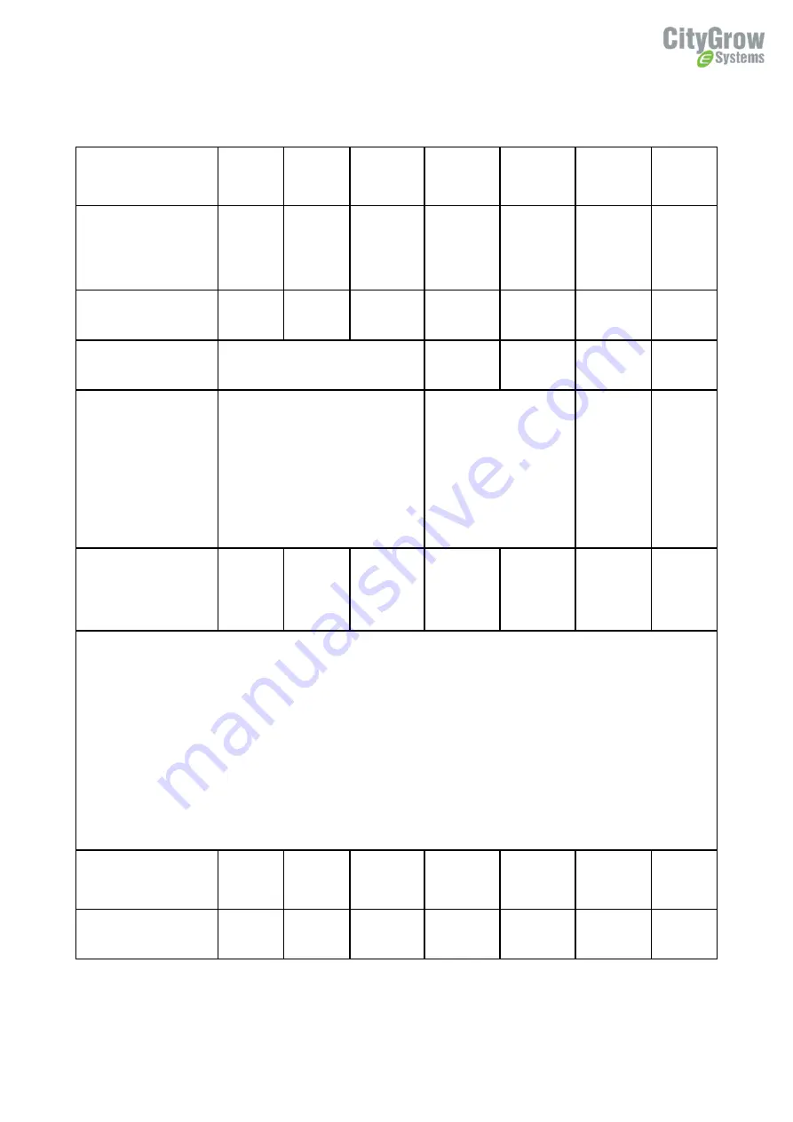
Specification
CG800S1
CG800S2
CG800S4
CG800DM
CG800DM2
CG800S2-
CCP
CG800S4
-CCP
Description
One
Gang
Switch
Two
Gang
Switch
Four Gang
Switch
One Gang
Dimmer
(Leading
Edge
Dimming)
Two Gang
Dimmer
(Leading
Edge
Dimming)
One Gang
Curtain
Control
Switch
Two
Gang
Curtain
Control
Switch
Load current (A)
10A
5A x 2
2.5Ax4
600W
300W x 2
5A
5Ax2
Minimum Load
NA
5W
5W / gang
NA
NA
Load type
Incandescent, Halogen, Electronic
( Solid State) Low Voltage (ELV)
Transformers, Magnetic ( Iron Core,
Inductive) Low Voltage ( MLV)
Transformers, Fluorescents, Compact
Fluorescents, LEDs, Motors
1.
Incandescent,
Halogen, Magnetic
(Iron core, Inductive)
Low Voltage (MLV)
Transformers,
2.
Leading Edge
Dimmable
Fluorescents,
Compact
Fluorescents and
LEDs, see remarks 3.
4.
AC motor
AC motor
Maximum number of
devices included in scene
setting** ( Remarks 1, 2)
50
50
50
50
50
NO
NO
**Remarks:
1.
When up button is used for dimming up function, the down button cannot be programmed as scene function
2.
Maximum number of devices programmed into the whole product is limited to 50 devices
3.
The maximum load requirements for fluorescent, CFL and LED loads can vary greatly depending upon the specific
fixture and /or bulb being used.
4.
When dimming transformer is connected to CG800, make sure “dimmable” and “leading edge” type is used.
Furthermore, the dimming performance varies greatly from manufacturer to manufacturer of the bulb and the
dimming transformer. It is recommended to test the matching performance before mass deployment.
Minimum dimming level
setting
NO
NO
NO
YES
YES
NO
NO
Memory dim function
NO
NO
NO
YES
YES
NO
NO


