CK-PAD2.0 Hardware-based Interactive Whiteboard User Manual
- 7 -
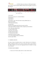
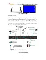
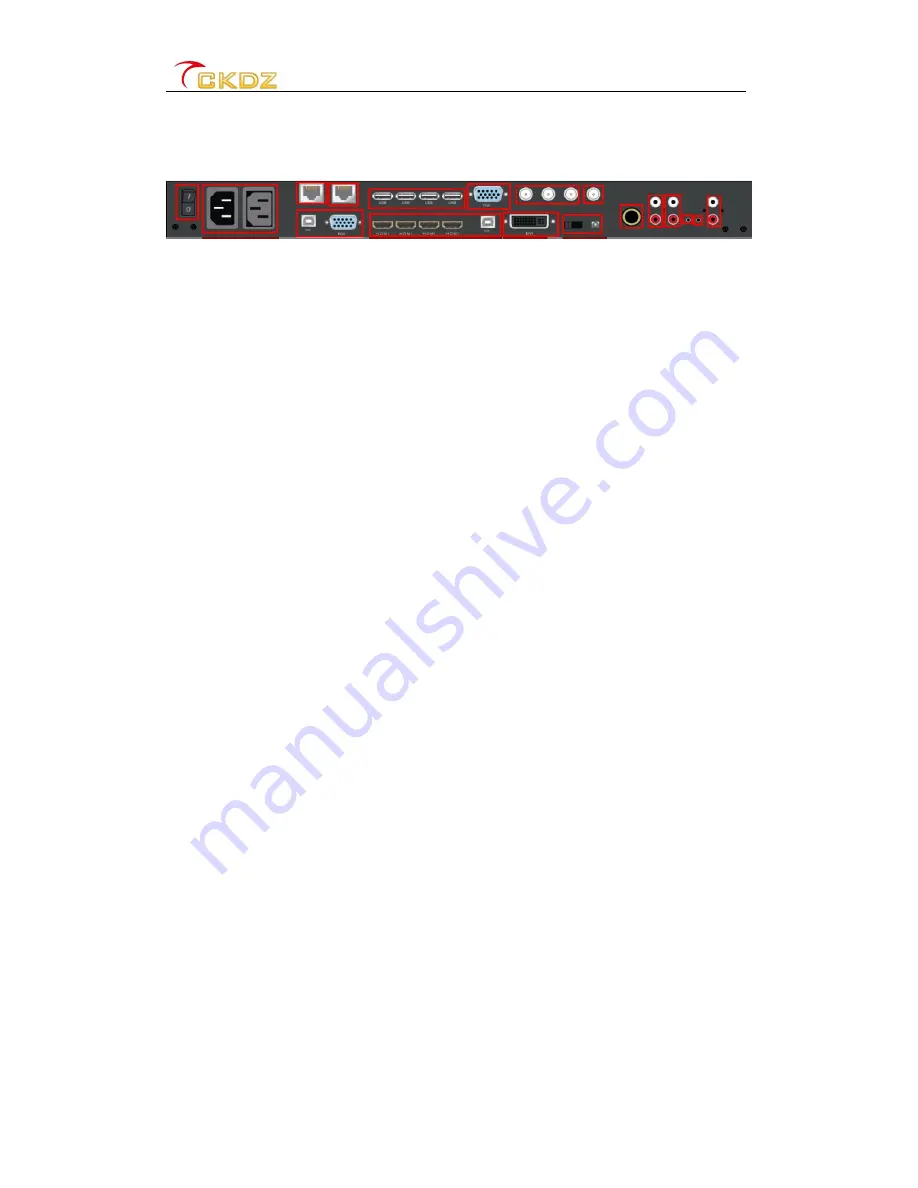
sources, users can refer to the below indication. Please contact our engineer if you are not
clear about this.
1 2 3 4 5 6 7 8 15 17
9 10 11 12 13 14 16 18
Fig 4.3 Rear panel view
1, Power switch;
2, Power loop-out socket, 100 ~ 240V AC 50/60 Hz;
3, WAN interface;
4, LAN interface;
5, USB interface, may connect with infrared, printer, USB flash disk, etc.;
6, Booth input interface;
7, YPbPr signal input interface;
8, CVBS interface;
9, External PC VGA signal input interface and mouse interface;
10, External PC HDMI input interface and the corresponding mouse interface;
11, DVI \ VGA signal output interface;
12, Software upgrade switch;
13, Microphone input interface;
14, YPbPr audio input interface;
15, CVBS audio input interface;
16, External PC audio input interface;
17, the corresponding booth audio input interface;
18, Audio output interface;
5. Installation instruction
Our product is based on hardware structure, so please firstly make sure the hardware is
already installed before switching on the power for flat panel. There are two methods for
CK - PAD2.0 installation, user can select the appropriate method of installation according
to the actual need.
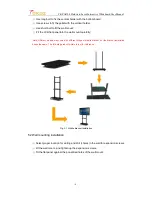
5.1 Mobile bracket installation
①
Use screws to fit the four wheels with four corners of bottom board;


