background image

                                                                              CK4L-5000 User Manual 

- 22 - 

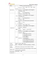
Model 

4L5000 Full color LED Video processor 

Signal output 

DVI/VG

Connector 

DVI-I

female

24+5

D-sub

female

15pin 

Resolution 

1024*768@60hz~2048*1080@60hz 

Color depth  32bits 

Sync 

HV independent sync 

Signal input 

VGA 

Connector 

D-sub

female

15pin 

Resolution 

640*480@60hz~1920*1200@60hz 

Color depth    32


Sync 

HV independent sync 

CVBS 

Connector 

BNC 

Resolution 

PAL/NTSC automatic identification 

Input 

impedance 

75

Ω


DVI 

Connector 

DVI-I

female

24+5 

Resolution 

1024*768@60hz~1920*1200@60hz 

HDMI 

Connector 

HDMI type 

Signal 

protocol 

HDMI 1.3

support HDCP 

Resolution 

1024*768@60hz~1920*1200@60hz 

YPbPr 

Connector 

BNC*3 

Resolution 

720

×

480i@59.94Hz/60Hz 

720

×

480p@59.94Hz/60Hz   

720

×

576i@50Hz   

720

×

576p@50Hz 

1280

×

720p@50Hz/59.94Hz/60Hz   

1920

×

1080p@50Hz/59.94Hz/60Hz   

1920

×

1080i@50Hz/59.94Hz/60Hz 

Control 

connector 

RS232 

D-SUB

female

9pin 

RJ45 

RJ45 female

10m/100m self-adaption

TCP/UDP 

Control 

software 

What you see is what you get control software is included 

Display mode   

It supports PIP,POP,Full screen,Overlay display etc..Video window 

size and location are adjustable. 

Power supply 

200-240VAC

  50Hz 

Consumption 


Summary of Contents for CK4L-5000

Page 1: ...multi pictures full color LED video processor User Manual V1 0 Shenzhen Createk Electronic Co Ltd http www ckdz com Note Please read the User Manual carefully before using the products and keep the m...

Page 2: ...WARE STRUCTURE 5 3 1 PRODUCT ELEVATION 5 3 2 REAR PANEL 5 3 2 FRONT PANEL 5 4 HARDWARE INSTRUCTIONAL MENU 6 4 1 FRONT PANEL BUTTON OVERVIEW 6 4 2 FRONT PANEL OPERATION 7 5 THE INSTRUCTION FOR CONTROL...

Page 3: ...CK4L 5000 User Manual ii 7 TECHNICAL SPECIFICATIONS 21 8 FAQ FREQUENTLY ASKED QUESTIONS 23...

Page 4: ...y missing If there is please contact the local supplier 3 Cut off the power if thunder or the machine is not used for long term 4 You should be well trained before operating the system 5 Do not slip a...

Page 5: ...LED screen d Four 4 spliced DVI outputs can realize max resolution up to 7680x1200 and can open 3 4 video windows if the sending cards are not cascaded 2 1 Basic function CK4L 5000 is developed to su...

Page 6: ...o 4 separate LED screens that could be in different Pitches such as P4 P6 P10 etc The videowall is fully scalable supporting a wide variety of display layouts such common 1x4 4x1 2x2 1x3 1x2 etc In th...

Page 7: ...one by one to the separate LED screen 2 3 2 Multiple inputs The video wall controller allows for inputs up to 20 different sources can show up to 4 different inputs simultaneously and can route any in...

Page 8: ...d capture technology allowing for any captured content to display full screen or partially 3 Hardware structure 3 1 Product elevation Fig 3 1 CK4L5000 product elevation 3 2 Rear panel Fig 3 2 Rear pan...

Page 9: ...splay layouts When SAVE is pushed you can adjust the Knob Button to increase or decrease the current preset mode from 1 16 4 RECALL Select the desired preset mode When RECALL is pushed you can adjust...

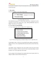
Page 10: ...ixels of LED screen A Input signal selection If you want the input 1 to show on window A output press the front panel button 1 the status display will show the current input 1 input 1 to output window...

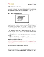
Page 11: ...isplay mode and two display 1x2 2x1 configuration mode Fig 4 4 2nd menu of Single display mode and two display 1x2 2x1 configuration mode In single display mode you can open or close the B C D video w...

Page 12: ...e 1 4 4 1 2 2 2 Resolution settings There are 9 kinds of resolution 1024 768 1280 1024 1366 768 1400 1050 1280 720 1600 1200 1920 1080 1920 1200 2048 1080 The field frequency is 60Hz 3 Image parameter...

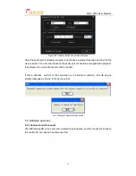
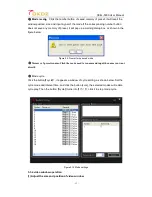
Page 13: ...5000Controller exe it appears the following interface Figure 5 2 Control software interface 2 Communication connection Select the item Setting in Communication setting setting area For the control of...

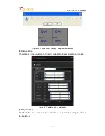
Page 14: ...n and application program then release the current serial port and reconnect If the Ip address conflict or the connection is in abnormal condition it would pop up prompt message as shown in the figure...

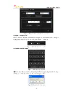
Page 15: ...e black screen and signal display the function is equal to the front panel button BLACK Figure 5 6 Close the black screen mode 5 3 3 Memory preset mode Figure 5 7 Mode operation interface A Mode Save...

Page 16: ...low Figure 5 9 Prompt for no saved mode C Memory of preset rename Click the mode need to rename and input the name you want directly D Mode cycle Click the button cycle it appears a window of cycle se...

Page 17: ...n drag it to change the window size when it turns into a two way arrow Figure5 11 Adjust the size and position of video window 2 Adjust the level of the video window Click the right mouse button and s...

Page 18: ...w and select Full Screen in the pop up menu Figure5 14 Full screen display 5 Open and close the video window Open the video window Click the right mouse button and and select Close window in the pop u...

Page 19: ...of X and the startY represents the start coordinate in the direction of Y Figure 5 17 Adjust coordinate value 5 3 5 Toolbar for system settings Figure 5 18 Tool button for system setting 1 System sett...

Page 20: ...t button 3 Color settings The setting is for the adjustment and reset of output brightness saturation and contrast Figure 5 21 The dialog box for color setting 4 Output settings Click the button Outpu...

Page 21: ...r different pitch size of LED display please select the smaller as refer point C LED box setting First set the LED screen pitch and click right side window namely current display box Then set the for...

Page 22: ...adjustment Select corresponding sending card and click the window need to adjust then adjust the video window size and location in pixel level 5 5 System menu There are four menus in the control softw...

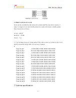
Page 23: ...It can be controlled by any other third party control device RS232 pin chart is as follows Pin Name Description 1 NC 2 TXD Single transmitter connect to device RXD 3 RXD Signal receiver connect to dev...

Page 24: ...00 00 00 00 00 00 00 00 00 Preset mode 4 F0 0F 0E 05 04 00 00 00 00 00 00 00 00 00 Preset mode 5 F0 0F 0E 05 05 00 00 00 00 00 00 00 00 00 Preset mode 6 F0 0F 0E 05 06 00 00 00 00 00 00 00 00 00 Pres...

Page 25: ...24 5 Resolution 1024 768 60hz 1920 1200 60hz HDMI Connector HDMI type Signal protocol HDMI 1 3 support HDCP Resolution 1024 768 60hz 1920 1200 60hz YPbPr Connector BNC 3 Resolution 720 480i 59 94Hz 6...

Page 26: ...tFX35setup exe and VisualBasicPowerPackssetup exe To download the program in Microsoft s official website 3 Can t run the control software 1 To confirm whether the COM port is right Check each compute...

Page 27: ...card is in normal work 2 To confirm whether the image is covered by sub window of PIP Attentions 1 The above listed is the common failure in after sales maintenance If you find the device failure phen...

Reviews: