CK4L-9000 Series User Manual
-
10
-
①
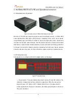
Power Socket: redundant power supply, AC220V 50 HZ,
②
Power switch: turn on the power switch and the equipment start to work normally
③
RS232 IN
:
Serial communication input, connected to computer or other control
equipment
④
RS232 OUT
:
Serial communication output, cascade to following equipment or other
equipment ;
⑤
Ethernet control: connect the devices to the internet for remote control.
⑥
interface
:
For usage later
⑦
Output ports: Signals are outputted to the video wall or cascaded to following
equipment;
⑧
Input ports: signal sources input, collect all kinds of sources.
(
AV,YPbPr,SDI,VGA,IP
Stream,DVI,DVI-X,HDMI etc..
)
(
Input cards are optional
)
Attentions: The above diagram is only for illustration; please refer to the actual rear panel.
3.4 Hardware operation instructions
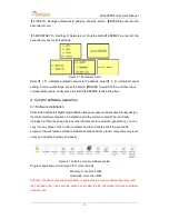
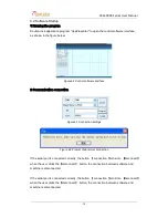
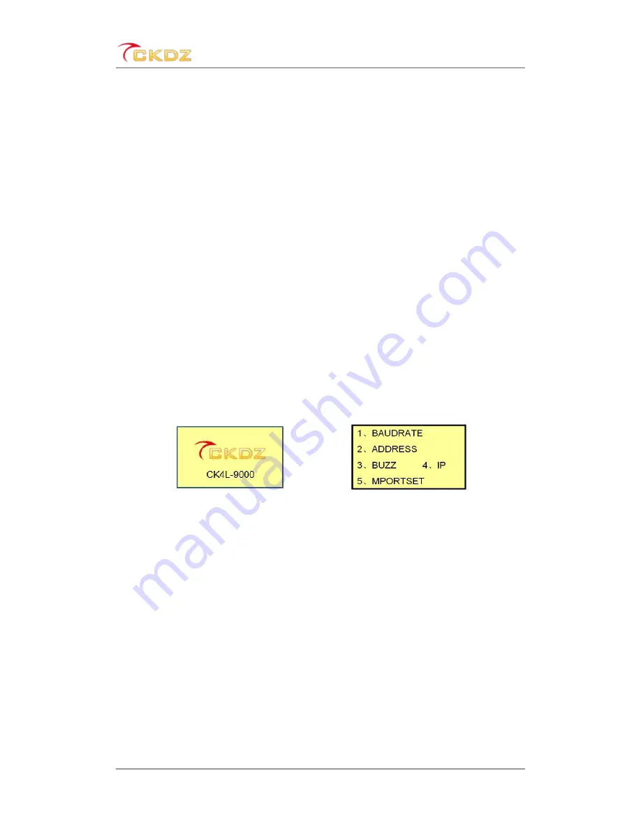
At normal state (do not press any key 12 seconds or more), the LCD screen display
content as shown below:
Figure 3.5At normal state
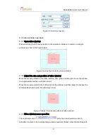
Figure 3.6 First level of the menu
Click the
【
MENU
】
button, it will appear first level menu ,as right-hand chart shown
above.
【
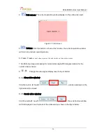
1.BAUDRATE
】:
Settings of baud rate, enter into the secondary menu by clicking the
【
ENTER
】
button, there are four optional in total:
【
1, 4800; 2, 9600; 3, 19200; 4, 115200
】
【
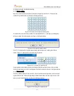
2.ADDRESS
】:
Settings of the address code: The screen will display
【
LOCAL
ADDR:001
】
after clicking the
【
ENTER
】
button. The default factory set is 001. The user
can adjust the value according to actual situation.
【
3.BUZZ
】:
Settings of Buzzer on/off., there are two options
【
1, BUZZ ON; 2, BUZZ
OFF
】
in the screen after clicking the
【
ENTER
】
button. Press the button
【
1
】
or
【
2
】
to control buzzer on or off;


