ARES 506-606 - 02.2005 - GB
G.19
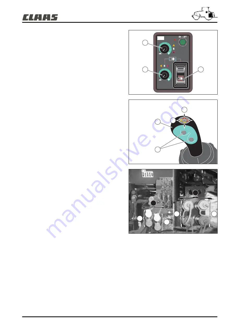
FLOATING POSITION
The two spool valves controlled by the Electropilot have a floating
position.
• Electro spool valve (A) ("y" axis):
- Push the joystick fully forward (beyond the "tight point") and
press the button (7).
- Release both controls. Spool valve No 5A is in floating
position.
• Electro spool valve (B) ("x" axis):
- Push the joystick fully to the right (beyond the "tight point")
and press the button (7).
- Release both controls. Spool valve No 5B is in floating
position.
Any displacement along the "x" or "y" axis will de-activate the
floating position on the corresponding axis.
ADDITIONAL FUNCTION
The impulse buttons (6) located on the knob of lever (1) are used
to control a bale elevator or other functions. To make the other
functions operational, call your approved CLAAS repair agent.
FLOW ADJUSTMENTS
Adjustment is made in the range from 5 to 100% of the available
flow. The flow on the electro spool valve (A) is adjusted with the
potentiometer (3). The flow on the electro spool valve (B) is
adjusted with the potentiometer (4).
Note: When connecting new implements, make preliminary
tests with a minimum flow setting (buttons (3) and (4) to a
stop, counterclockwise).
- To decrease the flow, turn the potentiometer to the left
(counterclockwise).
- To increase the flow, turn the potentiometer to the right
(clockwise).
391hsn08
391hsn06
395msn06
3
4
5
7
X
Y
6
5
B
A
5
A
B
Summary of Contents for ARES 546
Page 1: ...ARES 546 O 556 O 566 ARES 616 O 656 O 696 Use and Maintenance...
Page 2: ...CONTENTS...
Page 6: ...ARES 506 606 02 2005 GB Notes...
Page 9: ...ARES 506 606 02 2005 GB A 1 A IDENTIFICATION CERTIFICATION SAFETY...
Page 24: ...ARES 506 606 02 2005 GB A 16 Notes...
Page 25: ...ARES 506 606 02 2005 GB B 1 B CAB...
Page 46: ...ARES 506 606 02 2005 GB B 22 Notes...
Page 47: ...ARES 506 606 02 2005 GB C 1 C ELECTRICAL SYSTEM...
Page 53: ...ARES 506 606 02 2005 GB D 1 D ENGINE...
Page 61: ...ARES 506 606 02 2005 GB E 1 E TRANSMISSION...
Page 80: ...ARES 506 606 02 2005 GB E 20 Notes...
Page 81: ...ARES 506 606 02 2005 GB F 1 F FRONT AXLE...
Page 86: ...ARES 506 606 02 2005 GB F 6 Notes...
Page 87: ...ARES 506 606 02 2005 GB G 1 G HYDRAULICS LINKAGE AND REAR HITCH...
Page 111: ...ARES 506 606 02 2005 GB H 1 H FRONT POWER TAKEOFF LINKAGE AND FRONT COUPLING...
Page 116: ...ARES 506 606 02 2005 GB H 6 Notes...
Page 117: ...ARES 506 606 02 2005 GB I 1 I ON BOARD COMPUTER...
Page 125: ...ARES 506 606 02 2005 GB J 1 J WHEELS AND TYRES...
Page 140: ...ARES 506 606 02 2005 GB J 16 Notes...
Page 141: ...ARES 506 606 02 2005 GB K 1 K DIMENSIONS WEIGHTS CAPACITIES AND BALLAST...
Page 145: ...ARES 506 606 02 2005 GB L 1 L MAINTENANCE...
Page 173: ...ARES 506 606 02 2005 GB M 1 M OPERATIONS THAT ARE MANDATORY UNDER THE GUARANTEE...


