background image


PROXIMA STX


Ice-Cream Cabinet


ENGLISH


21 


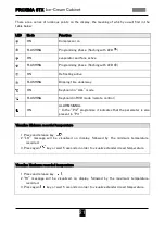
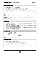
There are a series of luminous points on the display, the meaning of which you will find in the 
table below: 
 

LED 

Mode 

Function 


ON 

Compressor on 


FLASHING 

Programming phase  (flashing with LED  ) 


ON 

evaporator and fans active 


FLASHING 

Programming phase  (flashing with LED  ) 


ON 

Defrosting active 


FLASHING 

Dripping time underway 


ON 

Keyboard in “ALL” mode 


FLASHING 

Keyboard in RVD mode (remote control) 


ON 

ALARM SIGNAL 
- In the “Pr2” programme it indicates that the parameter is also 
present in “Pr1” 


Visualize Minimum recorded temperature  

 
1.


Press and release key  

2.


“LO”  message  will  be  visualized  on  display,  followed  by  the  minimum  temperature 

recorded. 

3.


Press again 

 key or wait 5 seconds in order to visualize standard read temperature. 


Visualize Maximum recorded temperature 

 
1.


Press and release key  

2.


“HI”  message  will  be  visualized  on  display,  followed  by  the  maximum  temperature 

recorded. 

3.


Press again 

 key or wait 5 seconds in order to visualize standard read temperature. 


Summary of Contents for FB Proxima STX A30

Page 1: ...Proxima STX gelateria English ...

Page 2: ...on 11 3 1 Lifting and Movement 11 3 2 Positioning 12 3 3 Environmental Specifications 13 3 4 Canalization 14 3 5 Plumbing connection 15 3 6 Electrical Connections 15 3 7 Water Drain Pipe 16 3 8 Remote Units Installation 17 3 9 End of Service and Disposal 17 4 Functioning 18 4 1 General Use Rules 18 4 2 Start up 19 4 3 Control panel 20 4 4 Alarm Messages 24 4 5 Cabinet with independent sector or wi...

Page 3: ...ed Maintenance Condenser Cleaning 28 5 4 Summary of scheduled Maintenance 29 6 Practical Troubleshooting Guide 30 7 Electrical Diagrams 33 7 1 Proxima STX Electrical Box 1 Semi Hermetic Compr 33 7 2 Electrical Box Condensing Unit Internal or Remote 34 8 Cooling System diagram 35 8 1 Cooling system w Double Inverted Cycle defrost 35 8 2 Optional Kit KVP Ice Cream Pastry Change 36 Rev 01 Year 2015 ...

Page 4: ... manual must be kept in good conditions and follow the cabinet during its entire operative life until dismissing in order to have all the information needed for maintenance of the qualitative and safety standards The Firm will not assume any responsibility for damage to people animals or things caused by failure to observe the indications reported on the present Manual or by uses of the equipment ...

Page 5: ...ng technical assistance try to fix the problem following the troubleshooting guide reported in the chapter n 6 If the problem cannot be fixed using the troubleshooting guide contact the authorized technical assistance using one of the following references Phone 39 0731 6153 1 Fax 39 0731 6153 413 Email info clabo it Or using Internet web site www clabo it It is necessary to communicate to the tech...

Page 6: ...osting system is automatic with double inverted cycle system two defrost cycles are realized separately regulated by electronic control with different time intervals Refrigeration is ventilated inside the cooled compartment the fans are installed and they produce air flow responsible for ice cream cooling The display case mod Proxima STX Ice cream cabinet has also a double air circulation system t...

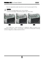
Page 7: ...ncentrated weight on the roof risk of Break In order to avoid damages distribute the weight evenly on the surface NO NO OK If the cabinet has a reserve storage this is designed for display of product at low temperature not below 18 20 C The storage is connected to an independent condensing unit and is managed by an additional electronic control ...

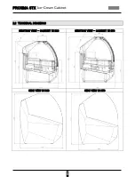
Page 8: ...PROXIMA STX Ice Cream Cabinet ENGLISH 8 2 2 TECHNICAL DRAWINGS SECTION VIEW CABINET H1320 SECTION VIEW CABINET H1450 SIDE VIEW H1320 SIDE VIEW H1450 ...

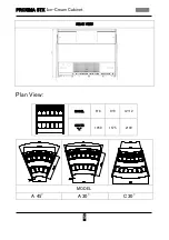
Page 9: ...PROXIMA STX Ice Cream Cabinet ENGLISH 9 REAR VIEW Plan View MODEL 6 6 9 9 12 12 QUOTE L 1050 1575 2100 MODEL A 45 A 30 C 30 ...

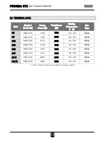
Page 10: ... G6 400 3 50 1150 1560 18 20 R404a G9 400 3 50 1700 2255 18 20 R404a G12 400 3 50 2170 2930 18 20 R404a A30 400 3 50 1150 1690 18 20 R404a C30 400 3 50 1150 1580 18 20 R404a A45 400 3 50 1210 1880 18 20 R404a G9 R 400 3 50 2050 2950 18 20 R404a G12 R 400 3 50 2300 3550 18 20 R404a Other electrical supply are available on customer request ...

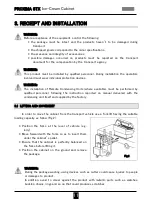
Page 11: ...available must be performed by qualified personnel following the instruction reported on manual delivered with the condensing unit itself and supplied by the factory 3 1 LIFTING AND MOVEMENT In order to move the cabinet from the transport vehicle use a fork lift having the suitable loading capacity as follow Fig 2 Position the forks at the level of vehicle e g lorry Move forward with the forks so ...

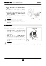
Page 12: ...pping Don t lift the cabinet more than 10 cm above the ground 3 2 POSITIONING For a correct positioning follow these instructions Position the display cabinet leaving enough space for use and maintenance in safe conditions as envisioned by the UNI EN 12100 2010 Check that there is a suitable earth plant present envisioned by European Standards Once positioned in the desired area make the display c...

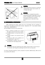
Page 13: ...denser are not blocked fig 6 Letter A air conditioning or heating in the room are not directed onto the display cabinet WARNING To guarantee the proper functioning of the cabinet let the air flow in a proper way to the customer side through the specific grid under the front covering panel The above mentioned indications must be respected to prevent malfunctioning which will not be covered by the w...

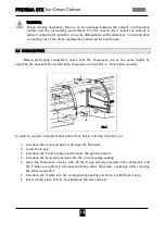
Page 14: ...ecial feet and that both showcases are laid flat i e horizontally levelled In order to join two cabinets follow instructions below referring to picture n 7 introduce the A pin and block it through the B dowels screw the E peg introduce the F and L plates and fix them through the dowels introduce the G crystal shoulder into the corresponding seating place the showcases side by side till the E peg a...

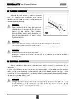
Page 15: ...ARNING Inlet water pressure can t exceed 10 bar Inlet water temperature shouldn t exceed 20 C in order not to decrease machine s performances 3 6 ELECTRICAL CONNECTIONS Before installation check that a suitable earth plant is present as envisioned by the regulations in force in the country of sale Check that the mains voltage is compatible with the features stated on the plate positioned on the op...

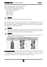
Page 16: ...abinet refer to chapter 2 Total Absorbed Power WARNING The electrical connection to the mains must be made using the five wires supplied Moreover the central plant to which the display cabinet is connected must have a switch with contact opening of at least 3 mm protected by fuses WARNING Apply a suitable method of fixing to the power supply cable on the connection box making reference to the tabl...

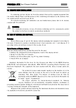
Page 17: ...he refrigerator circuit of the display cabinet Empty it of all of the oil it contains Remove all of the rubber parts e g O ring rubber trimming Send it off to be scrapped Important information for the User for the Purpose and effect of the WEEE Directive 2002 96 CE and subsequent amendments 2003 108 CE concerning Waste Electrical and Electronic Equipment this equipment has been marked with the abo...

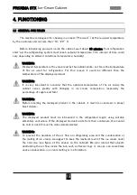
Page 18: ...er that the optimum temperature of the air inside the cabinet varies greatly with changing in ice cream composition especially the percentage of sugars and fats WARNING Before inserting the displayed product in the cabinet it must be conserved in proper blast chillers WARNING The displayed product must be introduced in the refrigerated region using suitable alimentary containers If the displayed p...

Page 19: ...tion of product inside For the same reason eventual air conditioning or warming systems should not blow directly air inside the machine Direct sun light shouldn t hit the cabinet in any time Sun radiation could damage the displayed product Nothing inside cooled compartment of the machine should block air flow WARNING In case of damage of the displayed product this one cannot be used or sold it mus...

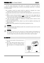
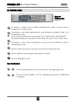
Page 20: ... pressed continually for 3 seconds this button allows the access to the sections menu This button is used during programming for going through the parameter codes or decreasing their value Keep this button pressed for 3 seconds to start the manual defrosting cycle Use this button to turn the display cabinet lights on and off Turn the refrigeration on off Keys Combinations Press and hold together f...

Page 21: ...board in RVD mode remote control ON ALARM SIGNAL In the Pr2 programme it indicates that the parameter is also present in Pr1 Visualize Minimum recorded temperature 1 Press and release key 2 LO message will be visualized on display followed by the minimum temperature recorded 3 Press again key or wait 5 seconds in order to visualize standard read temperature Visualize Maximum recorded temperature 1...

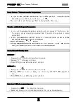
Page 22: ...n display will flash and temperature setpoint is visualized 3 Modify setpoint using or buttons 4 Confirm selected value pushing and releasing SET point one time The new value will flash three times Wait 15 seconds to come back to normal visualization Start a Manual Defrosting Cycle DEFROST 1 1 Press and hold button for more than 3 seconds 2 Message DF1 will appear on display 3 Press SET button and...

Page 23: ...nds until the message POF will appear and flash on display 2 At this point the keyboard is blocked and only setpoint and maximum minimum temperatures visualization are available 3 In order to unlock keyboard press and hold and button for some seconds until message Pon will appear and flash Stand By Function 1 Pressing ON OFF key OFF will be displayed 2 When OFF is displayed the machine enters the ...

Page 24: ...l installed in the base two different control boards with two keyboards will be present one for each sector main sector and second sector Reserve In order to use the second control the procedure are the same described above In case of presence of second sector not reserve the two control board are linked one each other in order to synchronize defrosting cycles the two cooled compartment of the cab...

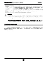
Page 25: ...vating the switch for passing in Pastry mode the programming parameter of the control board are NOT changed for this reason the cabinet will continue to work with same settings of Ice Cream functioning i e it will defrost at the same intervals Temperature Setpoint MUST be changed manually increasing it to 4 C if this operation is omitted the compressor will never stop with consequent possible dama...

Page 26: ... the end of the daily service of the shop WARNING During daily cleaning operations remove completely the displayed product from the cabinet In case of possible contacts between the products and not alimentary chemicals the product should be removed and wasted it can t be used or sold Glass Surfaces Clean glass surfaces back door front and side glasses shelves and roof top using a humid sponge and ...

Page 27: ... using a soft cloth WARNING Removing bottom panels you will get free access to the evaporators surfaces which are sharp and could injury the staff wear always suitable gloves when performing weekly cleaning 4 Use a humid sponge to remove any residual of ice cream product and dirt from the basin Avoid using too much water that could damage electric components WARNING Don t tamper or damage electric...

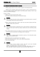
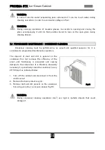
Page 28: ... by an expert and qualified operator for it is considered a programmed maintenance operation The deposit of dust and dirt in general on the condenser fins air reduces the efficiency of the plant until functioning is prevented and causing damage to the compressor It is therefore absolutely necessary to periodically clean the condenser every 20 30 days as indicated below 1 Turn off the cabinet and d...

Page 29: ...External glass surfaces X Daily Suitable cleaner Humid sponge Internal Glass surfaces X Daily Suitable cleaner Humid sponge Other External surfaces X Daily Suitable cleaner Humid sponge Inner basin surfaces X Weekly Humid Sponge Programmed Maintenance Generic Operator Qualified Operator Frequency Tools Condenser Cleaning X Monthly Brush Vacuum Cleaner ...

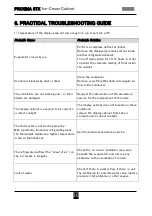
Page 30: ...st the intervention of the assistance service for the replacement of the same The display cabinet is exposed to air currents or direct sunlight The display cabinet does not function in these conditions remove the display cabinet from the air currents and or direct sunlight The thermostat is not working properly With a perfectly functional refrigerating plant the thermostat maintains a higher tempe...

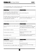
Page 31: ...ly level 3 The compressor never stops or it works for very long periods of time Probable Cause Probable Solution The room temperature is very high e g above 32 C If it is not possible to lower the room temperature e g by means of air conditioning the compressor will work almost constantly The air condenser is blocked Clean the condenser The thermostat is set too low Regulate the thermostat to a hi...

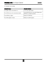
Page 32: ... Probable Solution The light switch is not turned on Turn on the light switch The LED bars are not connected properly Verify that the 4 pin connector between two LED bars is inserted properly The LED bar is blown Replace the LED bar The LED supplier is blown Replace the LED supplier ...

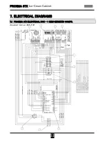
Page 33: ...PROXIMA STX Ice Cream Cabinet ENGLISH 33 7 ELECTRICAL DIAGRAMS 7 1 PROXIMA STX ELECTRICAL BOX 1 SEMI HERMETIC COMPR Standard Version 400 3 50 ...

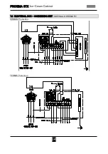
Page 34: ...PROXIMA STX Ice Cream Cabinet ENGLISH 34 7 2 ELECTRICAL BOX CONDENSING UNIT INTERNAL OR REMOTE KRIWAN Protection TERMIK Protection ...

Page 35: ...TION QUANTITY 1 Semi hermetic Compressor 1 2 4 way Defrost Valve 1 3 Condenser double fan 1 4 Condenser Fan 2 5 Liquid Receiver 1 6 Filter 1 7 Liquid Glass 1 8 Manual Tap 2 9 Check Valve 3 10 Thermostatic Valve 2 11 Evaporator Fan 3 5 12 Evaporator 2 13 Capillary diam 6 x 600 2 14 Second Defrost Solenoid Valve 1 17 HP Pressure stat 1 ...

Page 36: ...PROXIMA STX Ice Cream Cabinet ENGLISH 36 8 2 OPTIONAL KIT KVP ICE CREAM PASTRY CHANGE POS DESCRIPTION 1 Solenoid Valve Coil 2 Solenoid Valve Body 3 KVP Pressure Regulating Valve 4 Tee ...

Page 37: ...viati in garanzia o dei componenti difettosi sostituiti da rendere a Clabo Spa sono a carico del cliente WARRANTY TERMS Clabo Spa undertakes to provide warranty on its products to the first purchaser of the product for a period of 14 months running from delivery date The warranty acknowledgement is based both on the date of the delivery note and the serial number tag shown on the product Such docu...

Page 38: ......
Reviews: