background image

CLAGE 

15

EN

Model

CDX 7-U BASITRONIC® 

CDX 11-U BASITRONIC®

Energy efficiency class

A *

)

Rated capacity (Rated current)

6,9 kW / 10 A

11 kW / 16 A

Electrical connection

3~ / PE 380..415 V AC

Min. required cable size

1,0 mm

2

1,5 mm

2

Hot water (l/min)
max. at ∆t = 33 K

3,0

4,8

Rated volume

0,3 l

Type

Pressure type 1.0 MPa (10 bar)

Heating system

bare wire heating system IES®

Required spec. water
resistance @ 15 °C
Spec. electrical conductivity

≥ 1000 Ωcm

≤ 100 mS/m

Inlet temperature

≤ 30 °C

Flow rate to switch on – max. flow rate

2,0 – 4,0 l/min 

1)

2,0 – 5,0 l/min 

1)

Pressure loss

0,2 bar at 2,5 l/min       1,3 bar at 9,0 l/min 

2)

Temperature choice

50 °C (pre-set value 30 – 60 °C)

Water connection

G ⅜"

Weight (when filled w. water)

2,7 kg

VDE class of protection

I

Type of protection / safety

IP24

*) The declaration complies with the EU regulation No 812/2013

1) Flow rate limited to achieve optimum temperature rise
2) Without flow regulator

3. Technical specifications

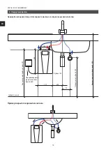
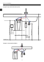
4. Dimensions

Maßangaben in mm

Summary of Contents for BASITRONIC CDX 11-U

Page 1: ...Installing instructions for the professional 10 17 ru 2 en 12 E compact CDX7 U CDX11 U E compact instant water heater CDX7 U CDX11 U...

Page 2: ...2 EN CDX7 U CDX11 U BASITRONIC 1 7 2 8 3 9 4 9 5 10 6 11 11 11 11 7 12 12 12 12 12 13 8 14 14 9 15...

Page 3: ......

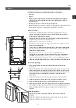
Page 4: ...Kabeleinf hrung Cable entry 4 2 38mm 6mm 600mm max 38 27 Anschlussraum Connection zone...

Page 5: ...312 108 37 177 100...

Page 6: ......

Page 7: ...CLAGE 7 EN 1...

Page 8: ...8 EN CDX7 U CDX11 U BASITRONIC 2 43 C www clage russia ru www clage com downloads...

Page 9: ...X7 U BASITRONIC CDX11 U BASITRONIC A 6 9 10A 11 16A 3 PE 380 415 1 0 2 1 5 2 t 33K 3 0 4 8 0 3 1 0 10 IES 15 C 1000 100 30 C 2 0 4 0 1 2 0 5 0 1 0 2 2 5 1 3 9 0 2 50 C 30 60 C G 2 7 VDE I IP24 812 201...

Page 10: ...10 EN CDX7 U CDX11 U BASITRONIC 600 294 177 70 75 100 G 108 850 550 600 5...

Page 11: ...CLAGE 11 EN 6 VDE 0100 EN 806 IP24 DIN16893 2 1000 15 C 1 2 3 4 5 6 6 5 7 1 2...

Page 12: ...12 EN CDX7 U CDX11 U BASITRONIC 7 VDE 0100 2 1 4 5 3 1 2 3 4 5 6 2 3...

Page 13: ...CLAGE 13 EN 7 1 2 3 4 5 6...

Page 14: ...14 EN CDX7 U CDX11 U BASITRONIC 8 1 10 30 2 3 4 CLAGE 50 C 30 60 C 2 55 C...

Page 15: ...CLAGE 15 EN 9...

Page 16: ...nstallation 16 6 Installation 17 Installation site 17 Mounting the appliance 17 Installing the appliance 17 7 Electrical connection 18 Wiring diagram 18 Structural prerequisites 18 Electrical connecti...

Page 17: ......

Page 18: ...Kabeleinf hrung Cable entry 4 2 38mm 6mm 600mm max 38 27 Anschlussraum Connection zone Cable entry...

Page 19: ...312 108 37 177 100...

Page 20: ......

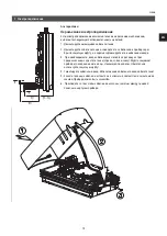
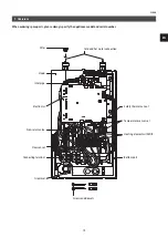
Page 21: ...cify the appliance model and serial number Bottom part Screws and dowels Temperature sensor set Heating element with SDB Safety thermal cut out Cold and hot water connection Hood Non return valve Elec...

Page 22: ...ate must be observed In case of malfunction disconnect the fuses immediately In case of leaks cut off the mains water supply instantly Repairs must only be carried out by the customer service departme...

Page 23: ...resistance 15 C Spec electrical conductivity 1000 cm 100mS m Inlet temperature 30 C Flow rate to switch on max flow rate 2 0 4 0l min 1 2 0 5 0l min 1 Pressure loss 0 2bar at 2 5l min 1 3bar at 9 0l m...

Page 24: ...00 294 177 70 75 100 G Example of an open outlet installation with special tap Example of a closed outlet installation Dimensions in mm Depth 108 Upper edge of the sink approx 850 Angle valve approx 5...

Page 25: ...nce of the water must be at least 1000 cm at 15 C The specific resistance can be asked for with your water distribution company Installation site 1 Thoroughly rinse the water supply pipes before insta...

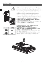
Page 26: ...the local electricity supply company The rating plate and technical specifications The unit must be earthed Wiring diagram 2 1 4 5 3 1 Electronic circuitry 2 Heating element 3 Safety pressure cut out...

Page 27: ...e cladding of the cable with the cord grip If necessary use one of the three predetermined breaking points for the cable entry at the right left or bottom The protective sleeve prevents water from ent...

Page 28: ...appliance The heating element will be activated after approx 10 30 seconds of water flow 2 Open the hot water tap Check the function of the appliance 3 Explain the user how the instantaneous water hea...

Page 29: ...collection point that accepts electronic scrap Disposing it correctly will support environmental protection and will prevent any potential negative effects on human beings and the environment that cou...

Page 30: ......

Page 31: ......
Page 32: ...s design changes and errors 9120 25636 10 17 CLAGE GmbH 21337 1 5 49 4131 8901 0 Telefax 49 4131 83200 E Mail service clage de Internet www clage de 129343 4 2 7 495 7418510 7 495 7418510 info clage r...

Reviews: