Zip HydroTap® G4 CS175
26
EN
4. Installation
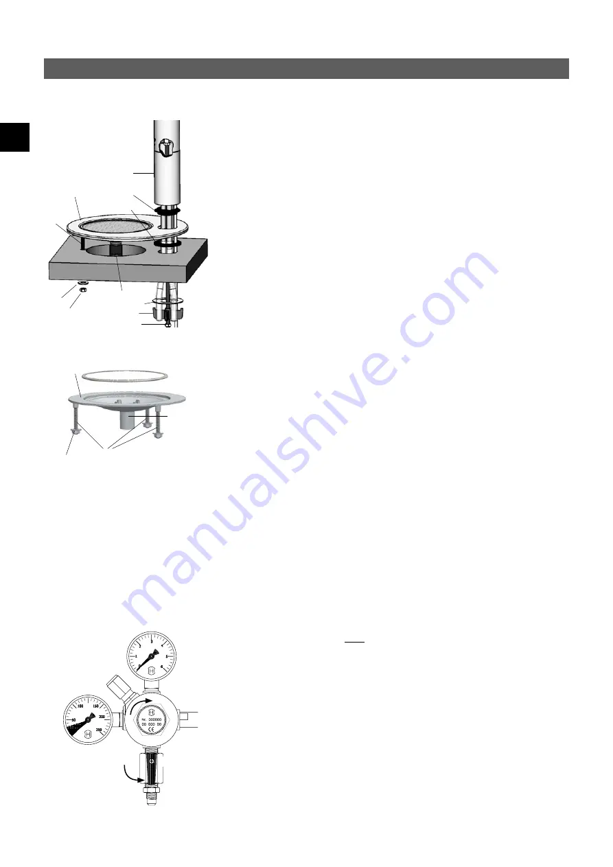
Tap
Spacer
Tray
threaded
rod
S/S washer
Drain pipe
Spider clamp
Fixing nut
Spacer
Washer
and fixing
nut
Optional: Installing the tray
The tray (article number: 4100-44111) is an accessory which can be used to install the
tap independently of a kitchen sink.
1. Ensure that a water supply, a drain, a socket fitted with at least a 10 A fuse and
enough room for the undersink unit are all available at the tray installation
location.
2. Place the template supplied over the tray installation location.
3. Cut out the holes as indicated on the template for an installation with a Classic or
Arc tap.
Classic
a. Insert the tray. Place the plastic spacer between the worktop and the tray at the
35 mm hole. Working from below, fasten the tray to the threaded rod using the
washer and fixing nut supplied.
b. Install the tap as described from point 3 onwards of “Installation Classic”.
c. If the drain bend is facing the wrong way, slacken off the fastening nut above
the bend, turn it to the correct position and then tighten up the fastening nut
again.
Arc
a. Insert the tray and fasten it to the threaded rods using the washers and fixing
nuts supplied.
b. Install the tap as described from point 3 onwards of “Installation Arc”.
4. Connect the drain bend to a siphon connecting sleeve, using a 22 mm diameter
hose. If no siphon connecting sleeve is available, use the snap connecting sleeve.
a. Place the snap connecting sleeve on the side of the siphon facing the sink. Drill a
13 mm diameter hole in the drain pipe behind the snap connecting sleeve for a
drain connection. Use a suitable sealant to make a watertight seal between the
snap connecting sleeve and the drain pipe.
1
2
A
B
Commissioning
1. Before using the unit for the first time, flush through the connecting pipes and
hoses thoroughly. To flush, detach the flexible hose from the water inlet of the
undersink unit and hold it over a drain or bucket. Turn on the water and allow it to
run for several minutes. Then reattach the hose to the water inlet of the undersink
unit and check the installation for leaks.
2. Set a outlet pressure ‘B’ of 3 bar on the pressure reducer:
a. Gas bottle with self closing valve: Turn the red lever ‘1’ down (open). To adjust
the outlet pressure ‘B’ use the adjusting screw ‘2’. Turn it anticlockwise to reduce
the pressure. Turn it clockwise to increase the pressure.
b. Gas bottle with hand wheel: Open the hand wheel valve at the CO2-bottle. The
pressure in the gas bottle will be shown in manometer ‘A’. Turn the red lever ‘1’
down (open). To adjust the outlet pressure ‘B’, use the adjusting screw ‘2’. Turn it
anticlockwise to reduce the pressure. Turn it clockwise to increase the pressure.
3. Check the gas-carrying connections for leaks. Caution - gas released can be very
cold. Use a leak detecting spray or soapy water so that even minor leaks will be
detected.
4. If no leaks are found, plug the plug into the socket and press the On switch on the
right-hand side of the undersink unit to activate the unit.
5. A prompt will appear on the display asking you to flush the carbonizer with carbon
Classic
Tab
Threaded
rod
Drain
Washer
and fixing
nut
Arc


