background image

Description of the generator

10

3.4.

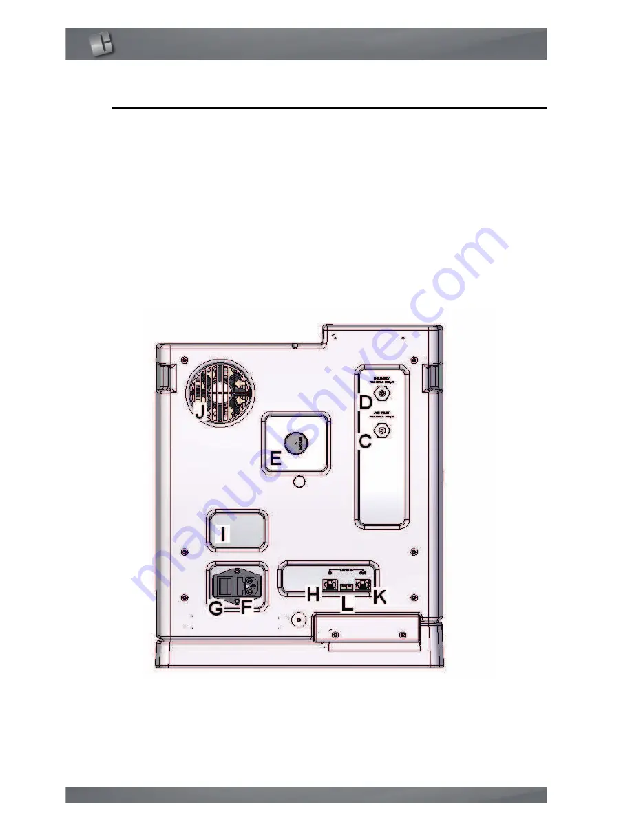
Rear view

C.  

AIR INLET: pneumatic connection for compressed air line inlet. 

D.  

NITROGEN OUTLET: pneumatic connection for the generator’s nitrogen 

delivery.

E.  

PRESSURE REGULATOR nitrogen delivery

F.  

CONNECTOR for electric power supply cable

G.  

POWER" KEY: ON-OFF switch; includes housing for the main fuse 

H.  

CAN BUS IN for connection to CPU

I.  

IDENTIFICATION LABEL: states the model, serial number (SN) and electrical 

specifications 

J.  

VENTILATION GRILLE

K.  

CAN BUS OUT

L.  

CAN BUS ADDRESS (DIP switch)

FIGURE 3.3.2. Rear view

Summary of Contents for AirGen

Page 1: ...User s Manual Nitrogen Generator NiGen GC Nigen MICRO ...

Page 2: ...ts 1 Introduction 3 2 Safety 4 3 Description of the generator 6 4 Installation 11 5 Disassembly and transport 16 6 Use 17 7 Maintenance 27 8 Troubleshooting 28 9 Guarantee 32 10 Declaration of conformity 33 11 Notes 34 ...

Page 3: ...ng models As regards installation and maintenance it is assumed that the user is familiar with pneumatic circuit components and in particular is aware of the safety as pects of compressed air and nitrogen The margin of the text contains the following symbols indicating m compulsory safety standards to be observed c electrical hazard e recommendations and important information It is strongly recomm...

Page 4: ...are stricter than what is described in this manual 2 1 Warnings m Place the generators FAR FROM SOURCES OF HEAT m Place the generators in an environment PROTECTED AGAINST RAIN AND WIND c NEVER OPEN the generator while it is connected to the electrical mains RISK OF FATAL INJURY BY ELECTROCUTION e Repairs and inspections must be carried out exclusively by QUALIFIED PER SONNEL in the event of faults...

Page 5: ...he control system constantly monitors the pressure In case of anomalous pressure a safety valve which operates independently of the control system prevents it exceeding 10 5 bar 152 psi MAXIMUM TEMPERATURE HC version only the purifier is fitted with an internal catalyser the temperature of which is constantly maintained at 420 C To guarantee safety a completely independent device is fitted which s...

Page 6: ... 2 check pin n 1 anchor plate n 2 fitting for the connection of the plastic tube external diameter 6mm n 1 fitting for the connection of the copper tube external diameter 1 8 3 2 Technical specifications 3 2 1 Nitrogen the flow rate is given at 20 C and 1 atm purity referred to residual oxygen Maximum flow rate NiGen GC 0 5 Nl min 0 5 slpm NiGen GC HC 0 5 Nl min 0 5 slpm NiGen MICRO 4 Nl min 4 slp...

Page 7: ...ty NiGen GC 6 Nl min 6 slpm NiGen GC HC 6 Nl min 6 slpm NiGen MICRO 12 Nl min 12 slpm Particulates maximum concentra tion of particles of diameter less than 0 1 µm less than 0 1 mg m Oil concentration less than 0 01 mg m Humidity dewpoint under pressure less than 3 C NiGen GC 115 230 V 10 1 ph 50 60Hz 50W NiGen GC HC 115 V 10 60Hz 1ph 200W or 230 V 10 50Hz 1 ph 200W NiGen MICRO 115 230 V 10 1 ph 5...

Page 8: ... cm 14 9 Depth 53 cm 20 8 Height 47cm 15 8 2 8 Weight NiGen GC NiGen MICRO 37 kg 82 lbs Weight NiGen GC HC 41 kg 90 lbs Installation site enclosed indoors Relative humidity up to 90 no condensation Use temperature from 5 C to 40 C from 40 F to 100 F Protection rating IP20 Noise level at 1 meter 60 dB A ...

Page 9: ...NiGen GC Nigen MICRO 9 3 3 Generator components 3 3 1 Front view A CPU generator control unit it is the user interface by way of the touch screen B FRONT PANEL removable for maintenance operations FIGURE 3 3 1 Front view ...

Page 10: ...nitrogen delivery E PRESSURE REGULATOR nitrogen delivery F CONNECTOR for electric power supply cable G POWER KEY ON OFF switch includes housing for the main fuse H CAN BUS IN for connection to CPU I IDENTIFICATION LABEL states the model serial number SN and electrical specifications J VENTILATION GRILLE K CAN BUS OUT L CAN BUS ADDRESS DIP switch FIGURE 3 3 2 Rear view ...

Page 11: ...it on the desk where you plan to install the generator e It is recommended to store the packaging to ensure adequate protection when moved in the future If the generator is to be installed on the tower see the attached 4 2 2 Positioning Position the generator on its support base two people are needed for this ope ration m Ensure a clearance of at least 20cm at the rear of the generator There must ...

Page 12: ...move the front panel and insert the check pline in the apposite holes the generator shall protrude of almost 20 cm so that the linchpins can be blocked by elastic splines 4 3 Pneumatic connections 4 3 1 Air inlet m The compressed air supply to the generator may not exceed 10 5 bar 152 psi CONNECTION Locate the compressed air inlet marked AIR INLET at the rear of the genera tor take fitting 1 2 and...

Page 13: ...the acceptable pressure drop values of the utility e To ensure nominal purity of the delivered gas is maintained minimize contami nation from oil residue dust scaling and humidity it is recommended to use clean and or treated metal pipelines for final gas distribution CONNECTION Locate the nitrogen coupling marked NITROGEN OUTLET at the rear of the generator take fitting 3 and mount it connect the...

Page 14: ...on Position the CPU where it will be used e g above the generator using the sup plied support connect the ethernet cable to the rear of the CPU top connector connect the ethernet cable to the rear of the generator CAN BUS IN connector ...

Page 15: ...ndations for correct installation do not use extension leads adaptors or multiple sockets always connect the protection ground wire the mains socket and switch must be located in an easily accessible position if the provided power cable does not match the local plug configuration the proper power cable with the appropriate configuration must be obtained prior to attempting to apply power to the un...

Page 16: ...e protection for the purifier when moved in the future 5 Disassembly and transport 5 1 Disassembly Stop the generator par 6 7 wait for depressurization about a minute switch off the generator par 6 8 disconnect the electric power cable close all valves air inlet tanks and detach the pneumatic connections 5 2 Transport e Remember that during transport the generator must always remain in a vertical ...

Page 17: ...isplay and set parameters The table shows the function of the various keys on the screen Key Function CPU access to CPU menu PREVIOUS go to previous page NEXT go to following page ALARM access to list of alarms WARNING access to list of warnings RESET reset of alarms and warnings MAINTENANCE go to maintenance request description MENU access to different menus ESC exit from menu ...

Page 18: ...ch screen with sharp objects START start the production of gas STOP stop the production of gas INCREASE increase the value DECREASE decrease the value ADD add one digit DELETE delete last digit OK confirms modified value Key Function ...

Page 19: ...Nitrogen Generator NiGen GC Nigen MICRO 19 6 2 Menus The following chart shows the accessible menus for the operator ...

Page 20: ...r 6 5 Generator start up 4 start nitrogen production by pressing the START key see par 6 6 Nitrogen production 5 wait approximately 15 minutes until the generator reaches the Stand By status In this state the generator suspends normal production showing the following page 6 from this point the nitrogen is available for the line by opening the valve closed in point 2 e For the model NiGen GC HC it ...

Page 21: ...the start button on the rear of the generator in position I the CPU screen lights up After the LOGO page is shortly displayed the GENERATORS LIST page appears Press on the generator of interest The READY TO START page appears 6 6 Nitrogen production To start production press the operation key START ...

Page 22: ...ture of the catalyst need reach at least 350 C if it doesn t reach this tempe rature there is a risk that the air isn t enought purified If the catalyst isn t operating the following page is displayed To reset the alarm press the RESET key 6 7 Stop the generator At any time during production the generator can be stopped by pressing the key STOP ...

Page 23: ...asts approximately one minute the display shows the following page 6 8 Generator shutdown After stopping the generator par 6 7 wait for the system to complete depres surization approximately 1 minute then put the main swotch on the rear of the generator in position 0 e Avoid turning off the generator directly without first stopping the production as described in par 6 6 ...

Page 24: ... of any changes before modifying the parameters 6 10 1 Adjusting the gas delivery pressure e the pressure can be adjusted from 0 to 6 bar 0 to 87 psi identify the delivery pressure regulator on the rear of the generator pull the pressure regulator knob out to release it set the pressure by turning the knob clockwise to increase counterclockwise to decrease it To visualize the outlet pressure see p...

Page 25: ... selection of different measuring units for temperature and pressure To perform the selection press the CPU key the following page appears Press MEASURE UNIT Select the desired measuring unit for pressure or go to the next page using the NEXT key Select the desired measuring unit for temperature ...

Page 26: ...ess the ESC key 6 11 Adjustment of the display contrast To increase the legibility of the LCD display press the CPU key the following page appears Press LCD CONTRAST Adjust to the desired value To exit this menu press the ESC key ...

Page 27: ...the following time intervals 7 2 Maintenance schedule e If a correct maintenance schedule is not followed the performance of the gene rator may no longer be ensured and it may lead to permanent damage to the generator e The maintenance operations must be carried out exclusively by QUALIFIED PER SON e Lack of maintenance will void the warranty The following table specifies the frequency of the reco...

Page 28: ...tervention of the operator but gas production is not shut down In WARNING status an acoustic signal is emitted the following page is displayed ERROR It indicates a condition that prevents continuation of gas generation The gen erator shuts down production and depressurizes the generation module In ERROR status an acoustic signal is emitted the LED on the front panel is intermittent red the followi...

Page 29: ...NG To visualize a warning message press on the WARNING symbol the following page will appear to find the active warning scroll down the pages using the NEXT key active warnings are those highlighted once the warning is identified follow the instructions in the following chapter To reset the worning press the reset key ERROR To visualize an error message press on the ERROR symbol ...

Page 30: ...roubleshooting 30 the following page will appear active errors are those highlighted once the error is identified follow the in structions in the following chapter To reset the alarm press the RESET key ...

Page 31: ...cording to table at par 7 2 1 W 03 catalyzer warm up time over the catalyzer has not rea ched the set point tempera ture contact service W 04 low catalyzer tem perature the catalyzer can not main tain the set point tempera ture contact service error identification cause resolution E 00 type error generator not identified assign a number to the generator see Stack user s manual E 01 low inlet press...

Page 32: ...premises The guarantee covers exclusively COSTS DERIVING FROM MANUFACTURING DEFECTS and does not include 1 Use of non original consumable or spare sparts 2 Damage caused by negligence or improper use of the equipment 3 Damage caused by inadequate electric power supply 4 Damage caused by natural catastrophes e g fire 5 Damage caused by transport 6 Damage caused by compressed air with inadequate pro...

Page 33: ... 50 60Hz alla quale questa dichiarazione si riferisce è conforme con quanto stabilito dalle seguenti disposizioni in particolare to which this declaration regards is fully in conformity with the following rules 2014 30 UE EMC Direttiva compatibilità elettromagnetica Electromagnetic compatibility directive 2014 35 UE Direttiva bassa tensione Low voltage directive 2014 68 UE Attrezzatura in pression...

Page 34: ...Notes 34 11 Notes ...

Page 35: ...Claind srl Via Regina 24 22016 Tremezzina Loc Lenno CO Italy Tel 39 0344 56603 Fax 39 0344 56627 e mail service claind it UM NiGen GC NiGen MICRO en G fm ...

Reviews: