31
❑
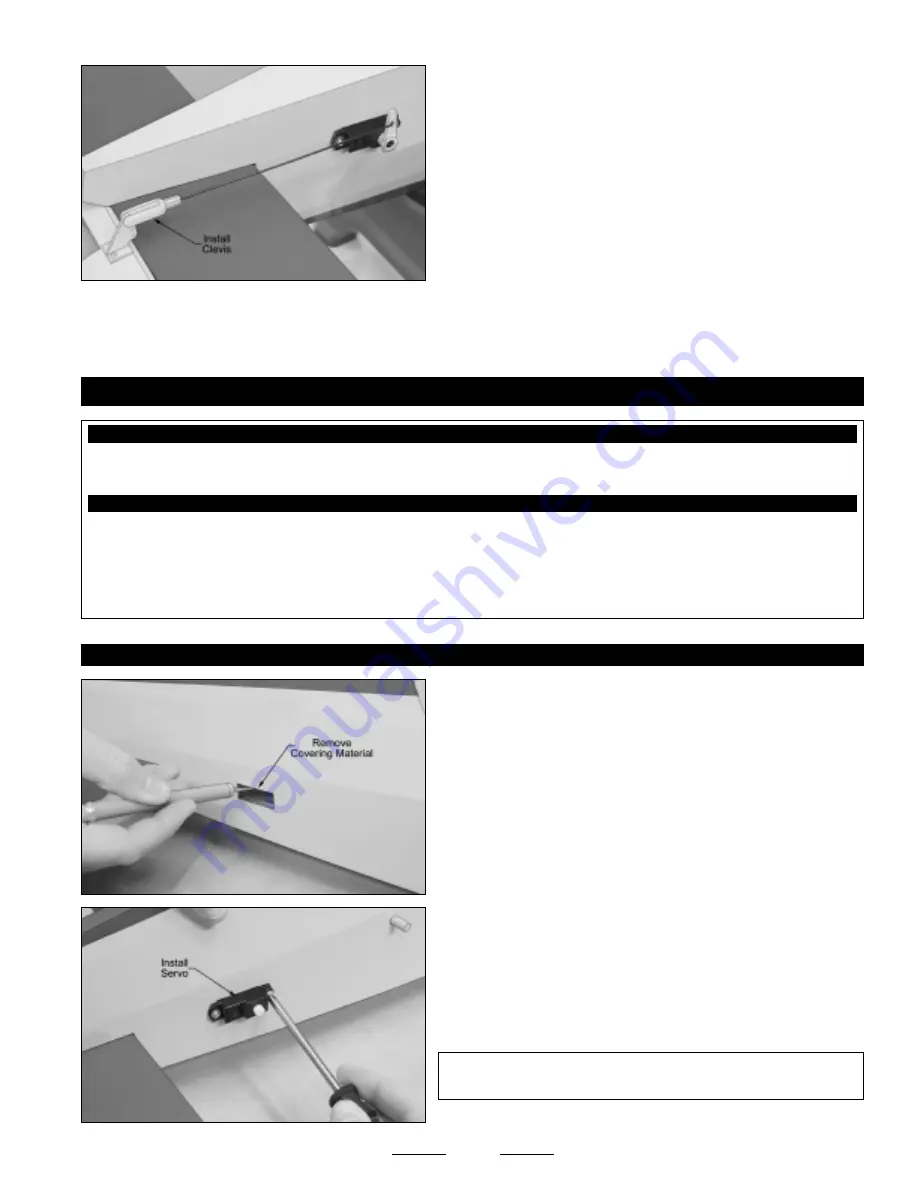
Thread the nylon clevis onto the pushrod wire and snap the clevis
into the
outermost hole
in the control horn.
☞
Hold the pushrod wire with a pair of pliers to prevent it from turning
or twisting when installing the clevis.
❑
Remove the masking tape from the elevator and double-check that
both the servo horn and the elevator are still centered. If the elevator
is not centered, adjust the clevis until it is.
❑
Move the elevator up and down several times to ensure that the pushrod assembly does not bind. It should operate smoothly in
both directions.
❑
Kwik Bond Thin C/A
❑
# 1 Phillips Head Screwdriver
❑
Needle Nose Pliers
❑
Excel Modeling Knife
❑
Electric Drill
❑
1/16" & 5/64" Drill Bits
❑
Ernst Airplane Stand
❑
Ruler
❑
Pencil
❑
Masking Tape
YOU'LL NEED THE FOLLOWING PARTS FROM THE KIT:
YOU'LL NEED THE FOLLOWING TOOLS AND SUPPLIES:
SECTION 16: RUDDER CONTROL SYSTEM INSTALLATION
❑
(1) 6-1/8" Threaded Wire w/Z-Bend
❑
(1) Nylon Control Horn w/Backplate
❑
(1) Nylon Clevis
❑
(2) M2 x 12mm Machine Screws
STEP 1: INSTALLING THE RUDDER SERVO
❑
Install the rubber grommets and brass collets onto your rudder servo,
making sure to install the collets with the flanges toward the
bottom
of
the servo.
❑
Install the rudder servo, making sure to drill 1/16" diameter pilot holes
for the mounting screws.
✦
✦
✦
✦
✦
IMPORTANT
✦
✦
✦
✦
✦
The servo output shaft should be toward the front
of the fuselage, as shown.
❑
Cut away and remove the covering material from over the rudder
servo mounting hole in the right side of the fuselage. The servo
mounting hole is located 6-1/4" in front of the rudder hinge line and
1-1-2" up from the bottom of the fuselage.
☞
Again, you may need to enlarge the hole to fit your rudder servo.
Continued On Next Page
☛
☛
☛
☛
☛


