background image


HDBaseT 4x4 Matrix Switcher User Guide 

11 

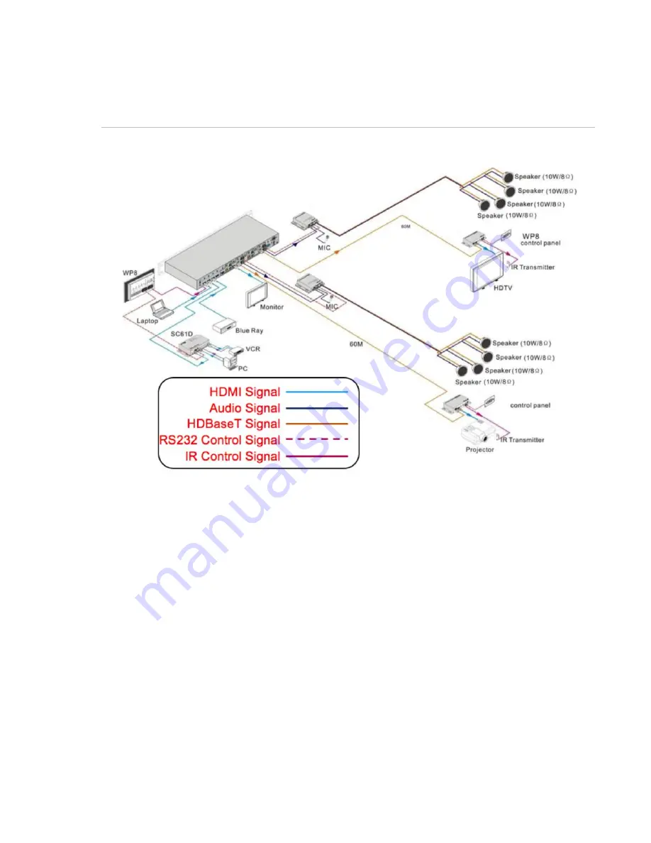
Application solution 

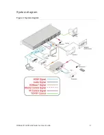
Figure 4: Solution diagram 


System operations


The button operation examples are shown in “

Error! Reference source not found.

 Here 

e make a brief  introduction to the system inquire operations. 

I/O control 

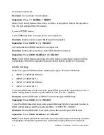
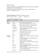
Convert an input to an output.   

Example:

 Input 1 to output 2. 

Operation:

 Press 

1 + 2 + SELECT 

Note:

 In default status, eight IR OUTs are corresponding with eight HDM INPUTS. 

When you  convert an HDMI input to an output, IR OUT switches synchronously. 
Convert an input to many outputs. 

Example:

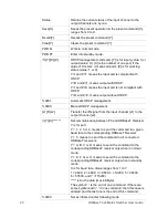
 Convert input channel 2 to output 2, 4, and 7. 

Operation:

 Press 

2 + 2 + 4 + 7 + SELECT


Summary of Contents for CM-MT4410-BT-70

Page 1: ...2014 12 352 Rev 03 HDBaseT 4x4 Matrix Switcher Model CM MT4410 BT 70...

Page 2: ......

Page 3: ...tents HDBaseT 4x4 Matrix Switcher Model CM MT4410 BT 70 name is a trademark of Clare Controls Inc Other trade names used in this document may be trademarks or registered trademarks of the manufacturer...

Page 4: ......

Page 5: ...l 5 Connection with RS232 communication port 6 Twisted pair cable connection 7 System connection 8 Usage precautions 8 System diagram 9 Connection procedure 10 System applications 10 Application solut...

Page 6: ...ii HDBaseT 4x4 Matrix Switcher User Guide Specifications 30 Troubleshooting and maintenance 32 Safety operation guide 34 After sales service 35...

Page 7: ...tial or incidental damages the preceding limitation may not apply to you In any event the total liability of Clare Controls Inc shall not exceed the purchase price of the product The foregoing limitat...

Page 8: ......

Page 9: ...P management HDBaseT outputs allow transmission of HDMI RS232 and IR up to 230 ft 70 m via Cat5e Cat6 cable allowing source equipment to be centrally located and shared between multiple display device...

Page 10: ...pter 48 VDC 1 x power cord 1 x IR remote 4 x 3 5 mm male mono to 3 5 mm male stereo IR adapter cable for use with a central control system 1 x RS232 male female cable for connection to a control syste...

Page 11: ...HDBaseT 4x4 Matrix Switcher User Guide 3...

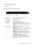
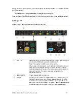
Page 12: ...uts Output buttons ranging from 1 to 4 7 Function buttons SELECT button Used to transfer HDMI and IR signal from an input to an output Example To transfer both HDMI and IR signals from input channel 1...

Page 13: ...Note This applies to all IR inputs on this switch When using a control system such as Clare Controls Crestron or URC the 3 5 mm female mono to 3 5 mm male stereo adapter cable included must be used Th...

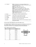
Page 14: ...t control 9 pin female connector 6 Power indicator Indicator light is on when the switch is powered 7 48 VDC Connection for external 48 VDC power supply 8 GROUND Bonding point to ensure equipment is p...

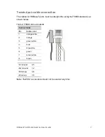
Page 15: ...aight thru using the T568B standard as shown below Table 2 T568B cable standards TIA EIAT568B Pin Cable color 1 orange white 2 orange 3 green white 4 blue 5 blue white 6 green 7 brown white 8 brown 1s...

Page 16: ...in a clean environment with the proper temperature and humidity controls All of the power switches plugs sockets and power cords should be insulated for safety All devices should be connected before p...

Page 17: ...HDBaseT 4x4 Matrix Switcher User Guide 9 System diagram Figure 3 System diagram...

Page 18: ...HDBaseT to the receivers as required 7 The CM MT4410 BT 70 can be controlled by the front panel buttons IR remote included a control system using IR signal via the IR EYE port RS232 or TCP IP 8 IR out...

Page 19: ...roduction to the system inquire operations I O control Convert an input to an output Example Input 1 to output 2 Operation Press 1 2 SELECT Note In default status eight IR OUTs are corresponding with...

Page 20: ...each button flashes quickly for 3 seconds EDID setting Select one type of EDID data from following four types of built in EDID data INPUT 1 1080P 2D PCM2 0 INPUT 2 1080P 3D 5 1 INPUT 3 1080P 2D PCM2...

Page 21: ...HDCP Y means the input signal is with HDCP N means it is not Check if the output is with HDCP Y means the output signal is with HDCP N means it is not Check the output resolution Use to check all eig...

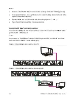
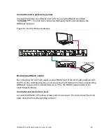
Page 22: ...g emitters are not supported You can control the switcher using its built in IR receiver or through the IR EYE port by connecting it to an extended IR receiver Or you can control it remotely using an...

Page 23: ...eT receiver then to the corresponding zone of the switcher through the twisted pair and finally transferred to the IR OUT port and received by the controlled device Switching operation Sending command...

Page 24: ...the received IR signal be transferred to the IR OUT port of the switcher When the IR receiver is connected with the HDBaseT receiver or the IR ALL IN port of the switcher is not with IR carrier send t...

Page 25: ...itcher Figure 8 Control remote devices through IR ALL IN port Control local device from remote User can control local device remotely such as video source device switcher etc When in use the IR signal...

Page 26: ...trol device Using the IR converting cable included connect the 3P end to the switcher s IR input port and then connect the 2P end to the IR output port of the third party control device The IR signal...

Page 27: ...sion Returns the firmware version installed MessageOff Turn off the feedback command from the COM port It displays switcher OK MessageOn Turn on the feedback command from the com port Demo Puts the sw...

Page 28: ...P 0801 Automatic HDCP management 0800 Manual HDCP management x1 R x2 Transfer the IR signal from the input channel x1 to the output channel x2 Y X Set communication between PC and HDBaseT Receiver Y i...

Page 29: ...status of the outputs 9973 Check the HDCP status of the inputs 9974 Check the HDCP status of the outputs 9975 Check the switching status 9976 Check the output resolution EDIDG x Get EDID data from th...

Page 30: ...e ending symbols and Type the command carefully It is case sensitive Control the HDBaseT 4x4 matrix switcher To control the HDBaseT 4x4 matrix switcher connect the female 9 pin of the RS232 port to th...

Page 31: ...onal RS232 control By connecting the one 3 pin captive screw RS232 port of the 4x4 matrix switcher with the PC or the controlled device and connecting the RS232 port of the corresponding HDBaseT recei...

Page 32: ...e Control the switcher by remote Connect the RS232 3pin captive screw port in one zone to control the third party device and then connect the PC to the corresponding receiver Figure 14 Control from re...

Page 33: ...68 0 178 Gateway 192 168 0 1 IP control port 4001 You can change the IP and gateway settings as needed Do not change the serial port number Connecting directly to a PC Connect a computer to the TCP IP...

Page 34: ...the switcher s IP address and gateway to the same IP section as the router 4 Set the PC s IP address and gateway as the original one 5 Connect the PC s to the router In the same LAN each PC is able t...

Page 35: ...erface The interface displays automatically when you log into the device To configure using the web interface 1 Click the Main tab and then click an input button and its corresponding output button Fo...

Page 36: ...e 3 Click the Interface tab to define a title bar label that displays on the switcher s front panel You can also label the inputs and outputs 4 Click the Configuration tab to turn on or off your HDCP...

Page 37: ...itcher User Guide 29 5 Select the Network tab to set the following parameters DHCP Subnet mask Static IP Gateway IP address 6 Click Save 7 Reboot the switcher Once rebooted you will be able to connect...

Page 38: ...0 Hz Switching speed 200 ns maximum Transmission distance 230 ft 70 m with PoC EDID management In built EDID data and manual EDID management HDCP Supports HDCP 1 3 auto and manual HDCP management Audi...

Page 39: ...P control Web based GUI General Power supply Input 100 VAC to 240 VAC 50 60 Hz Output 48 VDC 1 6 A Power consumption 48 W Temperature 4 to 158 F 20 to 70 C Humidity 10 to 90 Case dimension W H D 19 0...

Page 40: ...loss or poor picture quality Ensure that the HDMI cables used for both the source switch and the receiver display are properly connected and are working Test the HDMI cables directly from a source to...

Page 41: ...w video via the switch and all cables and sources and displays are working when bypassing the switch contact Customer Support for further assistance If the POWER indicator does not work or does not re...

Page 42: ...ntrol and ventilation The device generates heat when running Its environment should be well ventilated to prevent damage caused by overheating Disconnect power in humid weather or when left unused for...

Page 43: ...t be repaired a suitable replacement will be issued Replacement units will be comparable to the original However due to potential design changes over time replacement units may not be identical to the...

Page 44: ......
Reviews: