background image

Table of Contents

1.

About Your System  . . . . . . . . . . . . . . . . . . . . . . . . . . . . . . . . . . . . . . . . . . . . . . . . . . . . . . . Page 1

2.

Remote Transmitters

Remote Transmitter Layout  . . . . . . . . . . . . . . . . . . . . . . . . . . . . . . . . . . . . . . . . . . . .Page 2
Two Car Operation  . . . . . . . . . . . . . . . . . . . . . . . . . . . . . . . . . . . . . . . . . . . . . . . . . . .Page 3
Adding a New Transmitter into the System  . . . . . . . . . . . . . . . . . . . . . . . . . . . . . . . .Page 4
Deleting Transmitters  . . . . . . . . . . . . . . . . . . . . . . . . . . . . . . . . . . . . . . . . . . . . . . . . .Page 4
Battery Replacement . . . . . . . . . . . . . . . . . . . . . . . . . . . . . . . . . . . . . . . . . . . . . . . . . .Page 5

3.

Basic Operation

Remote Arming   . . . . . . . . . . . . . . . . . . . . . . . . . . . . . . . . . . . . . . . . . . . . . . . . . . . . .Page 6
Remote Disarming  . . . . . . . . . . . . . . . . . . . . . . . . . . . . . . . . . . . . . . . . . . . . . . . . . . .Page 7
Tamper Alert  . . . . . . . . . . . . . . . . . . . . . . . . . . . . . . . . . . . . . . . . . . . . . . . . . . . . . . . .Page 7
Silent Arming / Disarming . . . . . . . . . . . . . . . . . . . . . . . . . . . . . . . . . . . . . . . . . . . . . .Page 7
Arming Mode Selection . . . . . . . . . . . . . . . . . . . . . . . . . . . . . . . . . . . . . . . . . . . . . . . .Page 8
Passive Arming  . . . . . . . . . . . . . . . . . . . . . . . . . . . . . . . . . . . . . . . . . . . . . . . . . . . . . .Page 8
Panic Mode  . . . . . . . . . . . . . . . . . . . . . . . . . . . . . . . . . . . . . . . . . . . . . . . . . . . . . . . . .Page 8
Emergency Override  . . . . . . . . . . . . . . . . . . . . . . . . . . . . . . . . . . . . . . . . . . . . . . . . . .Page 9
Automatic System Rearming  . . . . . . . . . . . . . . . . . . . . . . . . . . . . . . . . . . . . . . . . . . .Page 9
Full Time System Diagnostics  . . . . . . . . . . . . . . . . . . . . . . . . . . . . . . . . . . . . . . . . . .Page 9

4.  

Other Features

Valet Mode  . . . . . . . . . . . . . . . . . . . . . . . . . . . . . . . . . . . . . . . . . . . . . . . . . . . . . . . . .Page 10
Ignition Controlled Door Locking / Unlocking  . . . . . . . . . . . . . . . . . . . . . . . . . . . . .Page 10
Dome Light Control . . . . . . . . . . . . . . . . . . . . . . . . . . . . . . . . . . . . . . . . . . . . . . . . . .Page 10
Auxiliary Function Outputs  . . . . . . . . . . . . . . . . . . . . . . . . . . . . . . . . . . . . . . . . . . . .Page 11
Remote Car Starter  . . . . . . . . . . . . . . . . . . . . . . . . . . . . . . . . . . . . . . . . . . . . . . . . . .Page 12
Garage Door Receiver . . . . . . . . . . . . . . . . . . . . . . . . . . . . . . . . . . . . . . . . . . . . . . . .Page 12
Additional Remote Transmitters   . . . . . . . . . . . . . . . . . . . . . . . . . . . . . . . . . . . . . . .Page 12

5.  

Reference Chart  . . . . . . . . . . . . . . . . . . . . . . . . . . . . . . . . . . . . . . . . . . . . . . . . . . . . . . . . .Page 13

6.  

Technical Data  . . . . . . . . . . . . . . . . . . . . . . . . . . . . . . . . . . . . . . . . . . . . . . . . . . . . . . . . . .Page 14

7.

Warranty  . . . . . . . . . . . . . . . . . . . . . . . . . . . . . . . . . . . . . . . . . . . . . . . . . . . . . . . . . . . . . . .Page 15

Note: Certain features described in this manual may require additional parts and/or labor.  Also, many features of

the Ungo MS3001 / MS3200 security systems have selectable options that must be activated or programmed
during the system’s installation.  These items will be identified in the following sections.  Your Authorized
Ungo Dealer will be happy to discuss these features with you and help you design your system to meet your
needs.

MS3001_owner's.qxd  9/10/99  5:27 PM  Page 3

Summary of Contents for UNGO MS3001

Page 1: ...MS3001_owner s qxd 9 10 99 5 27 PM Page 1 ...

Page 2: ...with your system s components and operation Discuss any questions you might have with your installing dealer Record the serial number of your Ungo system and keep all dealer records and receipts Be sure to discuss the installation with the dealer so that you understand the specifics of the installation in your vehicle Also do not forget to complete and mail the Product Warranty Registration Card w...

Page 3: ...nition Controlled Door Locking Unlocking Page 10 Dome Light Control Page 10 Auxiliary Function Outputs Page 11 Remote Car Starter Page 12 Garage Door Receiver Page 12 Additional Remote Transmitters Page 12 5 Reference Chart Page 13 6 Technical Data Page 14 7 Warranty Page 15 Note Certain features described in this manual may require additional parts and or labor Also many features of the Ungo MS30...

Page 4: ...sounds when system is triggered Battery Back up Siren MS3200 Water resistant self contained battery back up siren that sounds for up to 1 full hour when system is triggered or if the siren becomes disconnected from it s source of power Status LED red illuminated indicator that provides system status information Emergency Override Valet Switch used to override the system in case the Remote Transmit...

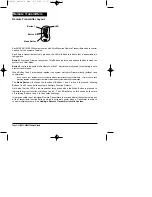
Page 5: ...his is done then pressing Buttons 1 and 2 together will Arm or Disarm the system with chirp confirmation The Mode Button will change the function of Buttons 1 and 2 when it is pressed allowing Buttons 1 and 2 to control the system s Auxiliary Function Outputs Note also that the LED on the transmitter turns green when the Mode Button is pressed to indicate the current function of Buttons 1 and 2 Th...

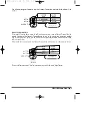
Page 6: ...you the convenience of operating multiple vehicles from a single Remote Transmitter When set for two car operation the Remote Transmitters will function as in the example below For more information about Two Car operation see your Authorized Ungo Dealer MS3001 MS3200 Owner s Manual Page 3 ARM DISARM AUX 1 AUX 2 MODE green MODE none BUTTON 1 BUTTON 2 MODE BUTTON Mode Sequence not used A Car 1 B Car...

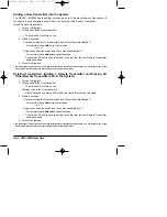
Page 7: ...nsmitter You may program any of the Transmitter s function buttons to arm and disarm the system at this point Deleting Transmitters Adding a Remote Transmitter and Erasing All Other Remote Transmitters From the System 1 Turn on the ignition 2 Press and hold the Override switch The status LED will turn on red Continue to hold the Override switch After 5 seconds the status LED will flash 4 times the...

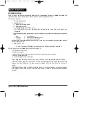
Page 8: ...mote Transmitter s battery is in need of replacement you will notice a decrease in your system s operating range or a decrease in the brightness of the Transmitter s LED indicator To change the battery remove the 2 screws at the back of the Transmitter and carefully separate the top and bottom halves of the Transmitter case Insert the new battery making sure that the positive and negative terminal...

Page 9: ...ll ignore that input but keep all other areas protected 3 After 20 seconds The LED will begin blinking indicating that the sensor inputs are activated While the system is Armed the system will trigger if The ignition key is turned on The doors are opened The Shock Sensor detects an impact to the vehicle or the motion of the car being raised The hood or trunk is opened A connected optional sensor i...

Page 10: ...triggered the system LED Flashes 60 seconds 1 flash door 2 flashes Shock Sensor 3 flashes optional sensor 4 flashes hood trunk example flash flash pause flash flash pause Shock Sensor Silent Arming Disarming Each Remote Transmitters can be individually set to Arm and Disarm the system with or without chirp confirmation at the time they are programmed into the system see Adding a New Transmitter in...

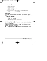
Page 11: ...chirp The parking lights will flash The doors will lock The status LED will flash red indicating the system is armed 4 The system is now armed The ignition must have been on for at least 4 seconds before the Passive Arming sequence will begin If the Passive Locking feature is selected To temporarily disable Passive Arming you can turn the ignition key on then off within 4 seconds The status LED wi...

Page 12: ...vity is detected within one minute One minute after Remote Disarming the system will alert you with a 10 second series of chirps then arm If the Passive Door Locking feature is selected during the installation the system will also relock the doors Any of the following will cancel Automatic System Rearming Turn on the ignition Open the Trunk or Hood Activate Auxiliary Function 1 or 2 Automatic Syst...

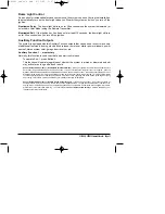
Page 13: ...to deactivate the Starter Disable circuit Ignition Controlled Door Locking For added convenience and safety this feature automatically locks your car s doors 10 seconds after the ignition key is turned on and unlocks the doors when the ignition key is turned off To set Ignition Locking Unlocking 1 Turn the ignition on 2 Within 4 seconds press Transmitter Button 2 The siren will chirp to indicate t...

Page 14: ...tive for as long as Button 2 is held Sensor Defeat with Auxiliary 1 Dedicated Remote Start Mode When your system is used with an optional Remote Car Starter Ungo model SAA4295 Auxiliary Function 1 can be selected to remotely start your car s engine With the MS3001 MS3200 s Dedicated Remote Start Mode enabled when Auxiliary Function 1 is used to activate the Remote Car Starter while the system is a...

Page 15: ...the Dedicated Remote Start feature designed into the MS3001 MS3200 the Remote Car Starter can be used to start your engine even while the system is armed When the Remote Car Starter is activated by an Auxiliary Function the system will receive a signal to temporarily ignore the Shock Sensor and the optional sensor inputs so that the system will not trigger due to the action of the car starting or ...

Page 16: ...lash after Tamper Alert door 2 LED flashes after Tamper Alert Shock Sensor 3 LED flashes after Tamper Alert optional sensor 4 LED flashes after Tamper Alert hood or trunk 1 chirp while armed Warn Away 5 quick chirps while armed Dedicated Remote Start Mode activated Double chirps 1 minute after disarming Automatic Rearming for 10 seconds LED flashing quickly ignition key off Passive Arming sequence...

Page 17: ...2v type 23A FCC ID MP62VUUUNGO1001 HP92VUUNGO603 03 THIS DEVICE COMPLIES WITH FCC RULES PART 15 OPERATION IS SUBJECT TO THE FOLLOWING TWO CONDITIONS 1 THIS DEVICE MAY NOT CAUSE HARMFUL INTERFERENCE AND 2 THIS DEVICE MUST ACCEPT ANY INTERFERENCE THAT MAY BE RECEIVED INCLUDING INTERFERENCE THAT MAY CAUSE UNDESIRED OPERATION Ungo Security Corporation Gardena CA USA Warranty Information Model No MS300...

Page 18: ... the warranty period The warranty period will be extended for the number of full days that the product has been out of the Owner s hands for warranty repairs If a defect exists within the warranty period the warranty will not expire until the defect has been fixed The warranty period will also be extended if the repair has not been performed due to delays caused by circumstances beyond the control...

Page 19: ...rporation A Clarion Company 661 West Redondo Beach Blvd Gardena CA 90247 800 Go Clarion www clarionmultimedia com Ungo Security Corporation Gardena CA 97 MS3001 10 Rev 3 1 99 MS3001_owner s qxd 9 10 99 5 27 PM Page 16 ...

Reviews: