5
ENGLISH
connection, preset 2 will be loaded. When the Profi le 2 terminal is grounded, Preset 3
will be selected. Finally, when both Profi le 1 and Profi le 2 are grounded, Preset 4 will be
selected. Audio will mute for a second or two while the settings are changed between
Presets.
Connection
Preset 1
Preset 2
Preset 3
Preset 4
Profi le 1
N/C
Ground
N/C
Ground
Profi le 2
N/C
N/C
Ground
Ground
SPEAKER LEVEL INPUT ADAPTERS
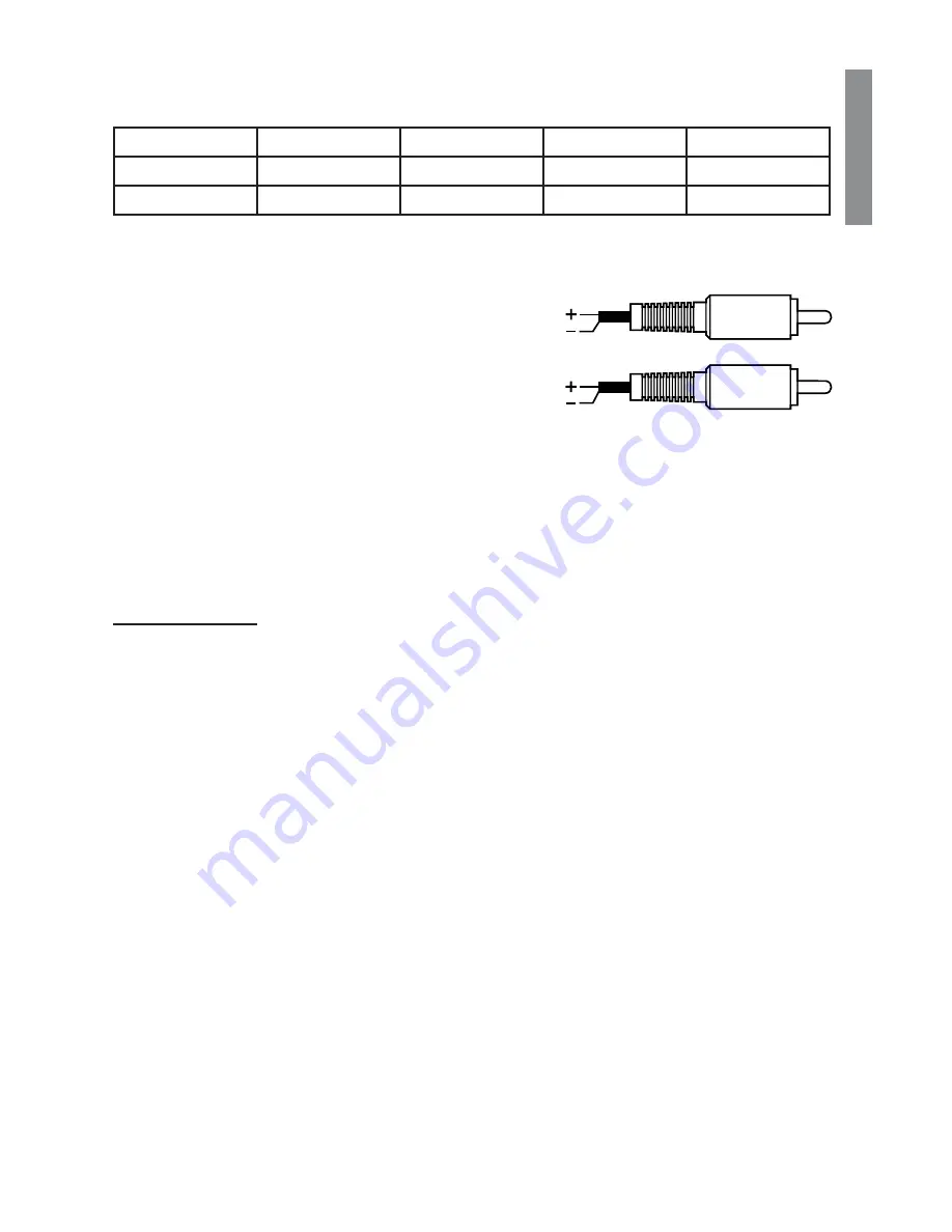
The RCA Input connections should be connected
to the RCA Pre-amp outputs of an aftermarket
head unit. If you are using a head unit or amplifi er
that only has speaker level outputs, please use
the high-level input adapters that are included
with the processor. Please wire them according to
the adjacent image. Note, there are components
in these connectors used to attenuate the signal. Do not substitute conventional RCA
terminals for these adapters or damage will occur. Damage from over-driving the input
stage of the XC660DSP is not covered under the manufacturer’s warranty.
NOTE: When connecting to the output of a factory amplifi er, you may need to install
load resistors on the amplifi er outputs to compensate for the output fi ltering circuit of the
amplifi er. A 50 Ohm, 5 Watt resistor usually works well.
INSTALLATION
1. Once a safe and suitable location has been chosen for your processor, locate and
mark the mounting hole locations.
2. Remove the processor and pre-drill the mounting holes.
3. Replace the processor and secure with adequate hardware.
4. If applicable, mount the BC2 remote in the front of the vehicle and run the included
wire to the connection on the processor.
5. Make all the power,control and signal to the processor.
6. Complete the remainder of the system installation and fi nish tuning the XC660DSP,
amplifi er and system.
Red
White
Red
Black
White
Blue


